
Method and device for achieving better heat transfer when using pulse heaters

a technology of pulse heater and heat transfer, which is applied in the direction of combustible gas production, gasification process details, combustion process, etc., can solve the problems that no other known method is capable of producing high-quality synthesis gas at unrivalled low cost, and achieves improved heat transfer, improved heat transfer, and improved heat transfer

Inactive Publication Date: 2009-04-02
SPOT SPIRIT OF TECHNOLOGY AG
View PDF4 Cites 26 Cited by
  • Summary
  • Abstract
  • Description
  • Claims
  • Application Information

AI Technical Summary

Benefits of technology

[0017]One possible field of application is the use of pulse heaters in the thermal gasification of biomass. No other known method is capable of producing a high-quality synthesis gas at unrivalled low cost, as a result of comparatively low investment costs, with CO2 reduction, or of utilising it as energy and simultaneously processing it into a fuel, after appropriate cooling and purification.
[0019]The advantage over fixed bed gasifiers and circulating fluidised beds is the absence of distinct temperature and reaction zones. The fluidised bed comprises an inert bed material. This thus ensures that the individual partial reactions take place simultaneously, as well as a uniform temperature (approximately 800° C.). The method is almost pressureless (up to a maximum of 0.5 bar) and can therefore be carried out in a problem-free manner from a technical point of view. It is characterised by high cost-effectiveness. The initial costs are lower than those of the aforesaid types of gasifier.
[0025]It can consequently be stated that the use of the subject matter according to the invention allows for a method in which 23 t high-quality fuel can be produced from 100 t biomass on the basis of the synthesis gas.
[0029]In this respect, swirl tubes are used for the heat exchanger tubes arranged downstream of the combustion chamber and acting like resonant tubes of a Helmholtz resonator. These are capable of drastically increasing heat transfer in the boundary layers determining the heat flow to be exchanged as a result of their geometrically deformed surfaces. The result is an additional improvement in heat transfer between the flue gas and the tube wall, resulting in the parallel use of both methods, i.e. pulsation and surface shape of the heat exchanger tubes, and an improvement and increase in heat transfer during part-load operation of the pulse heaters. This increase in the load performance leads to an improvement in and simplification of management. The increase in heat transfer moreover allows for a reduction in the number of pulse tubes while maintaining their serviceability. Reducing the corresponding number increases the lane width between the tubes, this additionally increasing heat transfer on the part of the fluidised bed.
[0030]As a result of this optimisation of material transport within the fluidised bed, heat transfer, as well as mass exchange and the reaction speed of the reactions during the gasification process are increased significantly.

Problems solved by technology

No other known method is capable of producing a high-quality synthesis gas at unrivalled low cost, as a result of comparatively low investment costs, with CO2 reduction, or of utilising it as energy and simultaneously processing it into a fuel, after appropriate cooling and purification.

Method used


Image

  • Method and device for achieving better heat transfer when using pulse heaters
  • Method and device for achieving better heat transfer when using pulse heaters
  • Method and device for achieving better heat transfer when using pulse heaters

Examples


Embodiment Construction

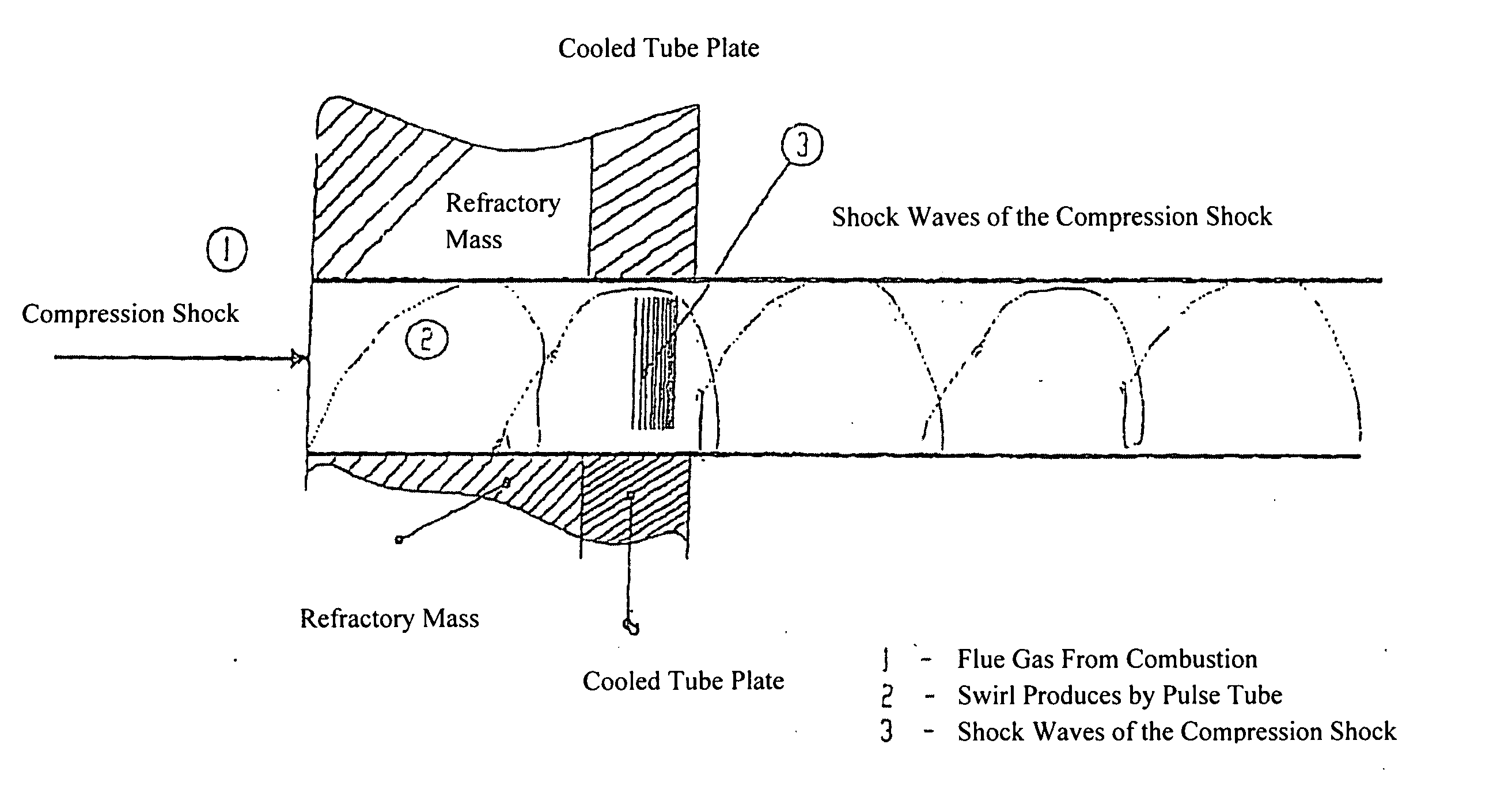
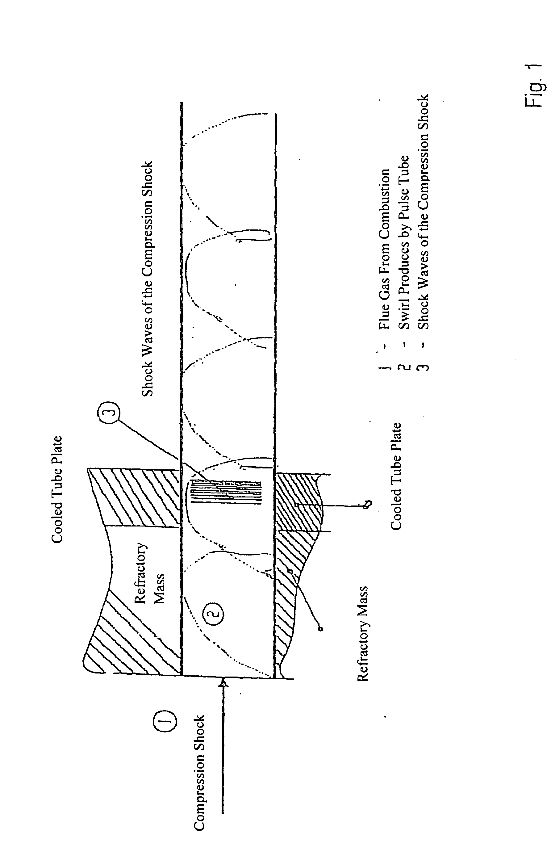
[0035]FIG. 1 shows a pulse tube 2 comprising embossing, so that the compression shock 1 produced by combustion results in a swirl. The shock waves of the compression shock 3 move spirally through the pulse tube. This is generally achieved in that embossed areas or bulges are formed within the pulse tube on the inside thereof, these converting the compression shock into a rotational movement. The pulse tube, which absorbs the compression shock 1, is initially surrounded by a refractory mass and is held by a cooled tube plate. As a result of the great heat of the compression shock, appropriate fixing is required and cooling is essential so that there is no damage to the burner.

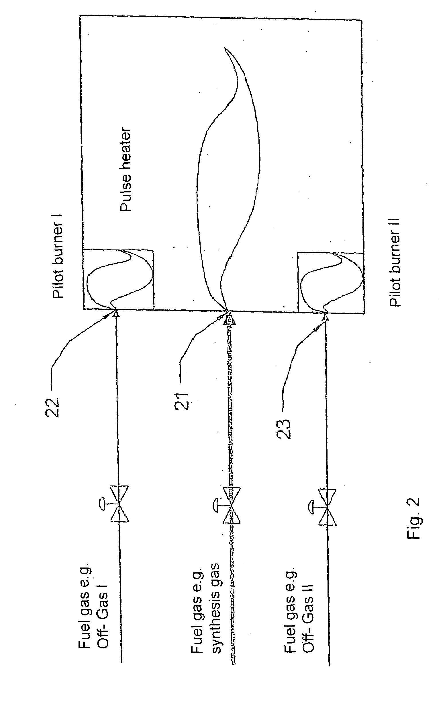
[0036]FIG. 2 shows a pulse heater 21 preferably used in a gasification reactor. The latter is additionally provided with a main burner operated with fuel gas, e.g. the synthesis gas produced by the gasification reactor. Two pilot burners 22 and 23 are furthermore provided, operated with fuel gas, e.g. off-gas I ...


PUM

PropertyMeasurementUnit
temperaturesaaaaaaaaaa
pressureaaaaaaaaaa
temperatureaaaaaaaaaa

Abstract

The invention relates to heat exchanger tubes acting like resonant tubes of a Helmholtz resonator and used as swirl tubes. They are capable of drastically increasing heat transfer in the boundary layers determining the heat flow to be exchanged as a result of their geometrically deformed surfaces.

Description

CROSS REFERENCE TO RELATED APPLICATIONS[0001]This application is a continuation of PCT / EP2007 / 052258 filed Mar. 9, 2007, which claims priority to DE 10 2006 017 355.4 filed Apr. 11, 2006, both of which are incorporated by reference.FIELD OF THE INVENTION[0002]The invention relates to a pulse heater and corresponding methods improving heat transfer in gasification processes.BACKGROUND[0003]The development of thermal gasification methods has produced essentially three different types of gasifier, namely entrained bed gasifiers, fixed bed gasifiers and fluidised bed gasifiers.[0004]Primarily fixed bed gasifiers and fluidised bed gasifiers have been developed further for commercial gasification.[0005]Of the many different technical approaches in the field of fixed bed gasification, the Carbo V method will be described by way of example here.[0006]Relevant literature for fluidised bed gasification, which forms part of this application, is as follows: “High-Temperature Winkler Gasificatio...

Claims


Application Information

Patent Timeline
Patent Type & Authority Applications(United States)
IPC IPC(8): C10J3/02F23J15/08C10J3/10C10J3/20B01J19/24B01J7/00B01J8/18F23D99/00
CPCC10J3/10F23C2205/00F23C10/12C10J2300/1261
Inventor NEUMANN, OLIVER
Owner SPOT SPIRIT OF TECHNOLOGY AG
Learn More