Liquid Container and Liquid Injection Device
- Summary
- Abstract
- Description
- Claims
- Application Information
AI Technical Summary
Benefits of technology
Problems solved by technology
Method used
Image
Examples
first embodiment
A. First Embodiment
(A1) General Configuration of Inject Recording Apparatus
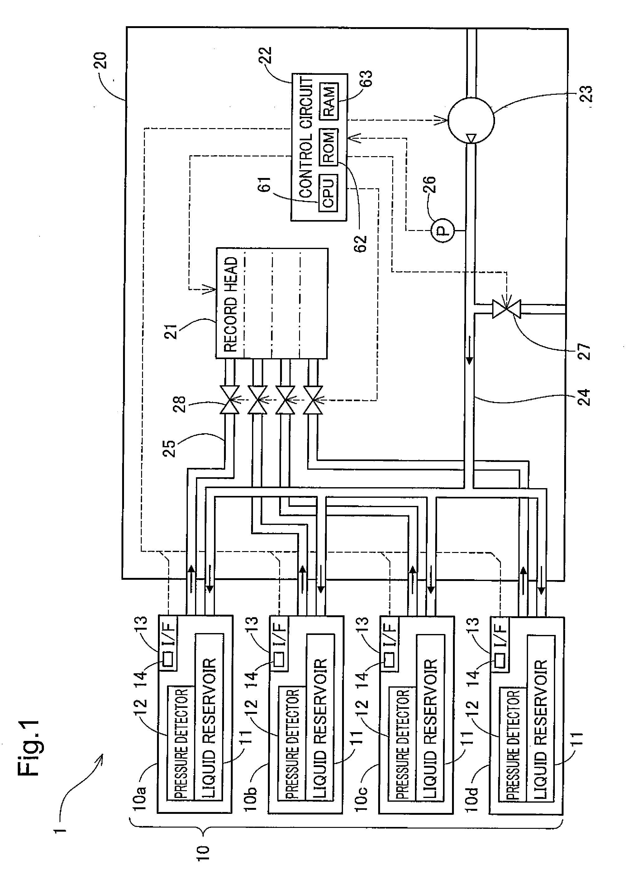
[0043]FIG. 1 schematically illustrates the configuration of an inkjet recording apparatus 1 in one embodiment of the invention. The inkjet recording apparatus 1 has liquid containers 10a to 10d and a liquid injection device 20. The liquid injection device 20 of the embodiment is designed to eject ink from a record head 21 onto a recording medium and thereby print images and strings of letters or characters. The liquid containers 10a to 10d are ink cartridges detachably attached to a container attachment of the liquid injection device 20 to supply respective inks to the record head 21 of the liquid injection device 20.
[0044]The four liquid containers 10a to 10d respectively storing inks of cyan, magenta, yellow, and black therein are attached to the liquid injection device 20 of the embodiment. These four liquid containers 10a to 10d have an identical structure and are collectively referred to as the liquid co...
second embodiment
B. Second Embodiment
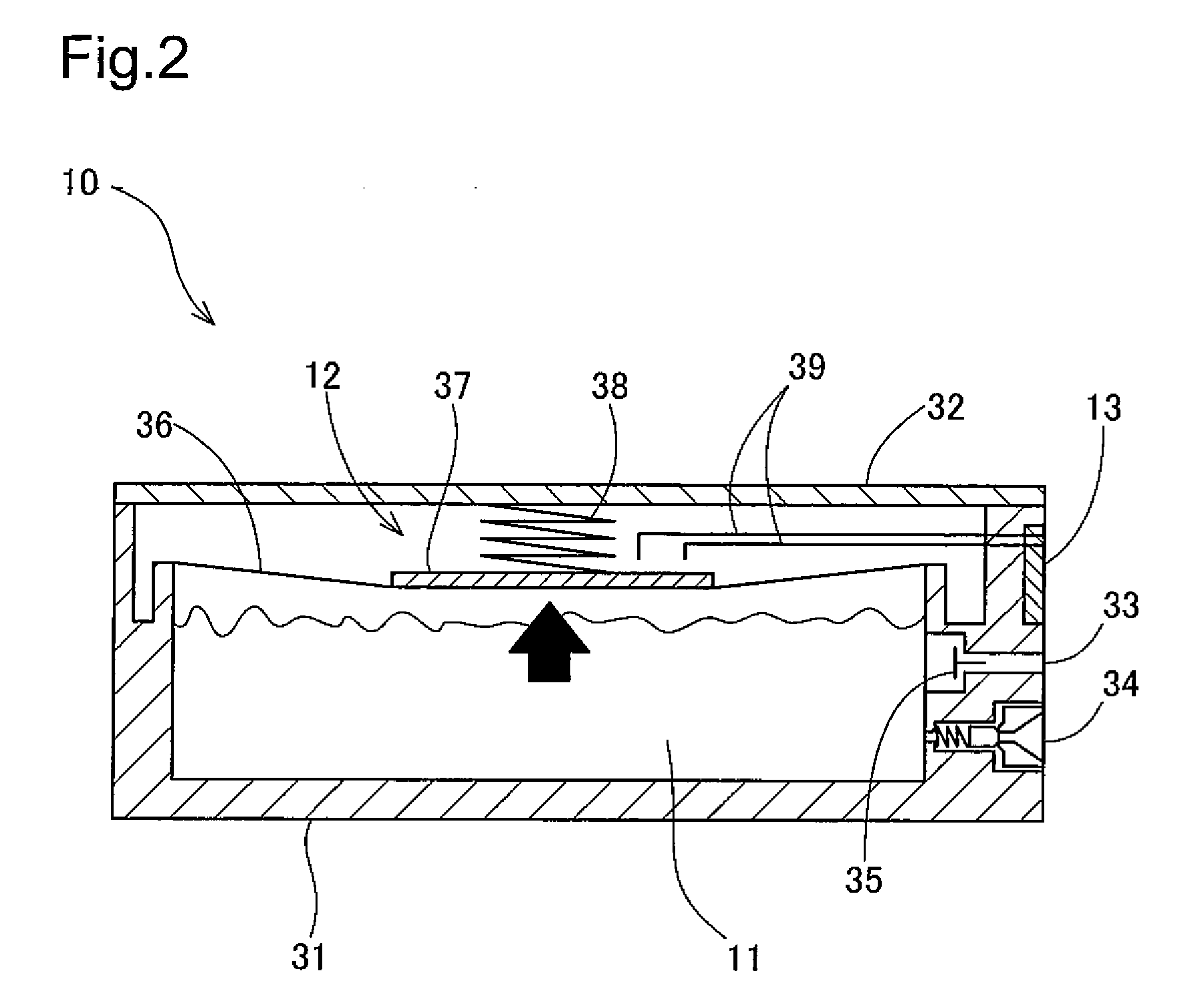
[0073]FIG. 4 is a sectional view showing a liquid container 10B in a second embodiment of the invention. In the liquid container 10B of the second embodiment shown in FIG. 4, the like elements to those of the liquid container 10 of the first embodiment shown in FIG. 2 are expressed by the like numerals. The liquid container 10 of the first embodiment has the flexible film member 36 provided on the top face of the liquid reservoir 11 to integrate the liquid reservoir 11 with the pressure detector 12. In the structure of the second embodiment, on the other hand, a liquid reservoir 11 is independently formed in the liquid container 10B. A pressure detector 12 is placed in an air conduit 40 connecting the liquid reservoir 11 with an air flow inlet 33. A check valve 35 is provided between the pressure detector 12 and the liquid reservoir 11 to prevent ink leakage through the air conduit 40.
[0074]The pressure detector 12 of the embodiment has a pressure detection chamb...
third embodiment
C. Third Embodiment
[0076]FIG. 5 is a sectional view showing a liquid container 10C in a third embodiment of the invention. The liquid container 10C of the third embodiment shown in FIG. 5 has the similar structure to that of the liquid container 10 of the first embodiment shown in FIG. 2, except a flexible ink pack 44 provided in the liquid reservoir 11. The ink pack 44 is filled with ink in a liquid tight condition. The ink pack 44 is formed by bonding the peripheries of two aluminum laminate films. Each aluminum laminate film is formed as a laminate of a flexible resin film layer and an aluminum layer. One end of the ink pack 44 is connected with a liquid supply inlet 34. Ink is supplied from the liquid supply inlet 34 to the record head 21 of the ink injection device 20.
[0077]In the liquid container 10C of the third embodiment, an air flow inlet 33 communicates with an enclosed space in the liquid reservoir 11 defined by the ink pack 44, a casing 31, and a film member 36. When th...
PUM
 Abstract
Description
Claims
Application Information
 - R&D
- Intellectual Property
- Life Sciences
- Materials
- Tech Scout
- Unparalleled Data Quality
- Higher Quality Content
- 60% Fewer Hallucinations
Browse by: Latest US Patents, China's latest patents, Technical Efficacy Thesaurus, Application Domain, Technology Topic, Popular Technical Reports.
© 2025 PatSnap. All rights reserved.Legal|Privacy policy|Modern Slavery Act Transparency Statement|Sitemap|About US| Contact US: help@patsnap.com


