
Removable Wallboard System

a wall panel and wall panel technology, applied in the direction of walls, covering/linings, constructions, etc., can solve the problems of difficult positioning of electrical, mechanical and structural features behind the wall panel, time-consuming and labor-intensive, and therefore expensiv

Inactive Publication Date: 2009-03-26
PETTINE THOMAS +1
View PDF0 Cites 21 Cited by
  • Summary
  • Abstract
  • Description
  • Claims
  • Application Information

AI Technical Summary

Benefits of technology

[0024](a) to provide a less complicated wall system for constructing walls;
[0043](t) to provide a wall system which allows for quicker, cleaner and easier retail, office, restaurant and commercial wall modifications; and

Problems solved by technology

Present drywall installing, hanging and finishing methods do not provide accessibility behind the wall, are time-consuming and labor-intensive and therefore expensive.
Electrical, mechanical and structural features behind the wall panels are difficult to locate.
Once located these are difficult to access.
Damaged panels results in replacement and wasted time.
These systems provide limited use.
All panels are just 8 feet tall and they come in only one finish and only one color, are difficult to install and are expensive to construct.
They are not suited for drywall or for finishing interior walls.
These systems do not produce the soft and warm finish necessary when finishing interior residential and office space.
These systems also are expensive to construct.
It becomes time consuming to calk, wait for it to dry, then sand the wall panels with this system.
The calking typically crumbles as it is removed; creating calking powder and a mess that is required to be cleaned.

Method used


Image

  • Removable Wallboard System
  • Removable Wallboard System
  • Removable Wallboard System

Examples


Embodiment Construction

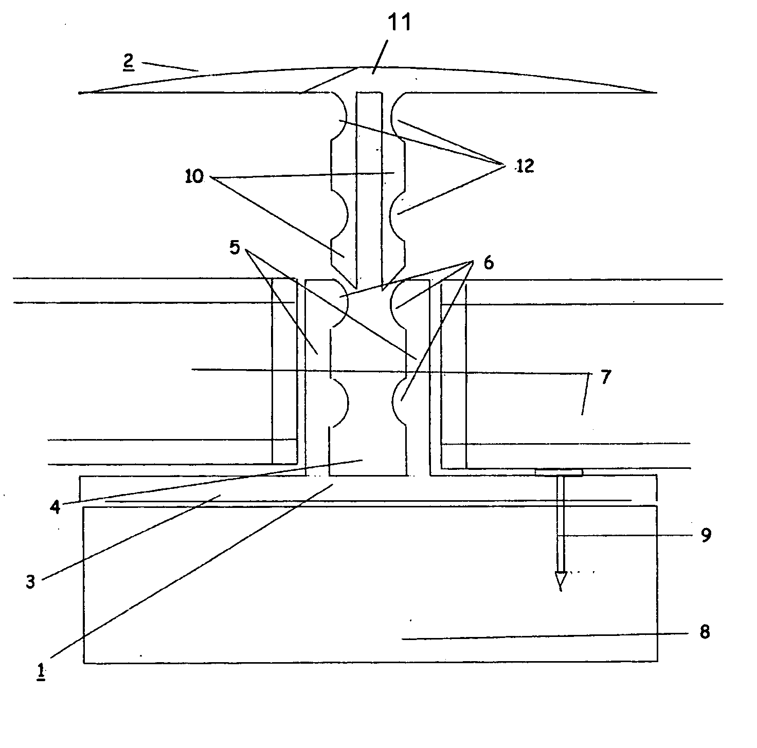
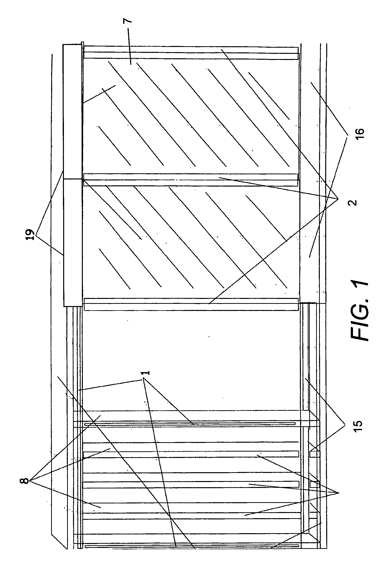
[0068]FIG. 1 is a perspective view of a section of a room having partially installed walls using the system of the present invention. A plurality of frame members 8 are installed using a traditional installation method.

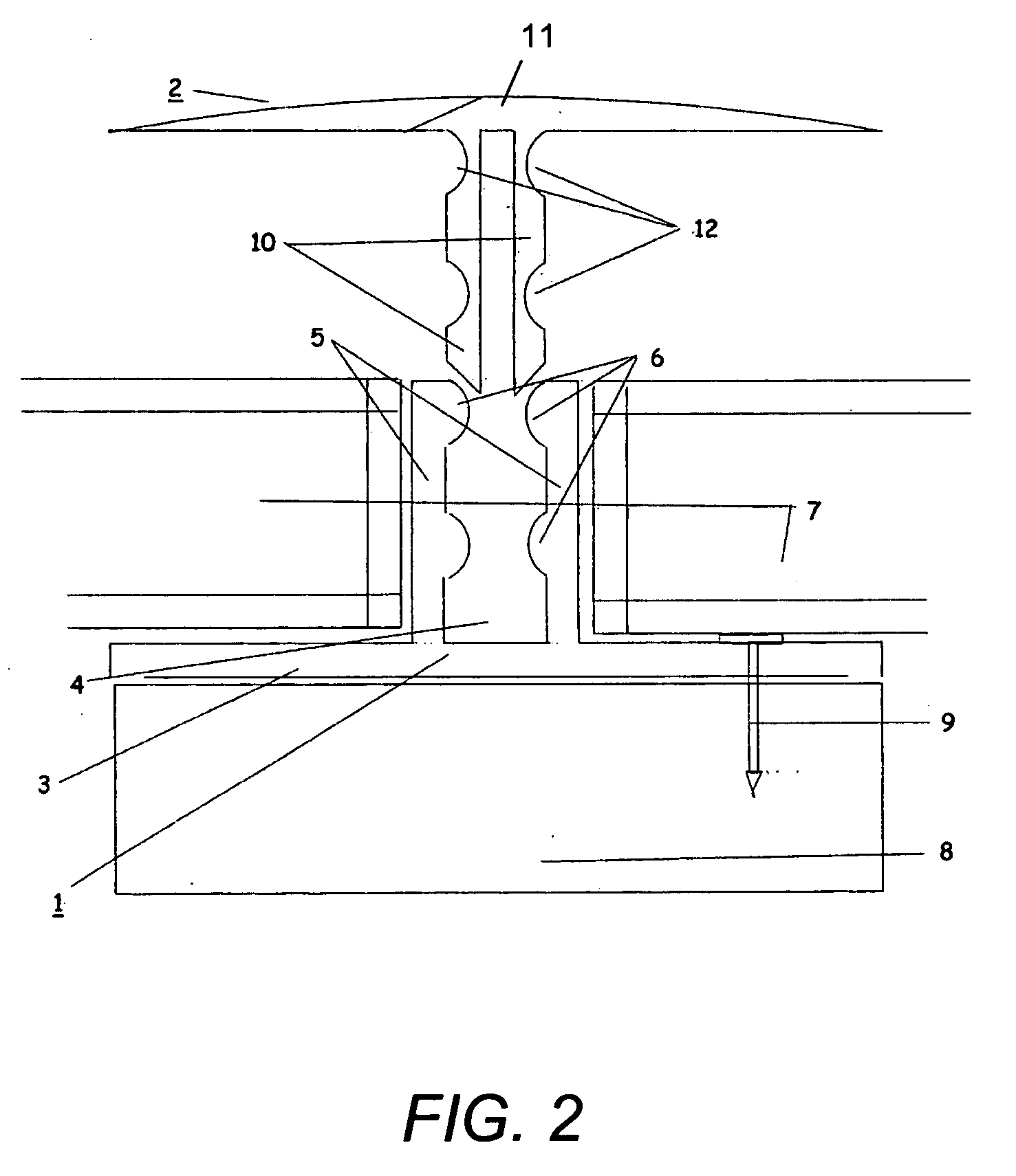
[0069]Multiple receiver strips 1 are attached to support frame members 8 a specific distance apart. Wall panels 7 are positioned adjacent to a receiver strip 1 and held in place.

[0070]Trim units 2 are pressed into the receiver strips 1 such that they secure wall panels 7. Trim units 2 also act to cover the vertical seams.

[0071]Wall panel 7 is typically made of gypsum, commonly called drywall. Since this drywall is inexpensive and plentiful, this system is very cost effective. Other types of panels may also be used.

[0072]A receiver strip 1 is installed horizontally at floor height.

[0073]Base molding 16 is pressed into receiver strips 1.

[0074]Similarly, a receiver strip 1 is mounted horizontally at ceiling level. A crown molding 19 is pressed into receiver strip 1 near ...


PUM


Abstract

The present invention is a novel removable wallboard system. It includes a plurality of receiver strips [1] which are attached to framing members [8] of a structure to be paneled. Each receiver strip has a receiving channel [4]. Wall panels 7 are placed snugly between the receiver strips [1]. Trim units [2] are elongated strips having insertion strips [10] which are designed to fit into and be retained by receiving channels [4] of the receiver strips [1]. Since the trim units [2] are designed to have a low profile, and they cover the seams between the wall panels [7], there is no need for further finishing or caulking. Therefore, these wall panels [7] may be removed and replaced with minimal effort or cleanup. The system also includes easily installable, removable and replaceable base molding [16], crown molding [19], and chair rail molding [29]. These may be designed to create chase ways [18, 74] allowing hidden routing of electrical, utility cables, pipes and hoses. Since the system may interactively be constructed and removed, it is useful in business settings in which offices are constantly adjusted.

Description

CROSS REFERENCE TO RELATED APPLICATIONS[0001]This application is a Continuation-In-Part of U.S. Provisional Patent Application 60 / 995,678 “Removable Wallboard System” by the same inventors as this application. It therefore, claims priority from the filing date of this earlier-filed Provisional Patent Application being the Sep. 26, 2008.FEDERAL SPONSORED RESEARCH[0002]Not ApplicableSEQUENCE LISTING OR PROGRAM[0003]Not ApplicableBACKGROUND OF THE INVENTION[0004]1. Field of the Invention[0005]This invention relates to a removable wallboard system for homes and businesses.[0006]2. Discussion of Prior Art[0007]Present drywall installing, hanging and finishing methods do not provide accessibility behind the wall, are time-consuming and labor-intensive and therefore expensive.[0008]Drywall is installed as follows: A sheet of drywall is held up against a previously framed wall. The edges are normally nailed with drywall nails temporarily securing the sheet to the framed wall. The middle of ...

Claims


Application Information

Patent Timeline
Patent Type & Authority Applications(United States)
IPC IPC(8): E04B1/38E04B1/00
CPCE04B2/7457E04B2002/725E04B2002/7462E04F13/0814E04F19/067E04F19/022E04F19/061E04F19/062E04F19/02E04F19/064
Inventor PETTINE, THOMASJONES, HOWARD
Owner PETTINE THOMAS
Learn More