
Panic Exit and Enclosure Gate Method

a technology for exiting gates and enclosures, applied in the direction of fastening devices, mechanical devices, construction fastening devices, etc., can solve the problems of lack of safety, deficient current gates in several ways, and difficulties in the installation process of gates, so as to reduce labor and tools. the effect of delivery

Inactive Publication Date: 2009-03-19
JANGAR MFG COMPANY
View PDF20 Cites 2 Cited by
  • Summary
  • Abstract
  • Description
  • Claims
  • Application Information

AI Technical Summary

Benefits of technology

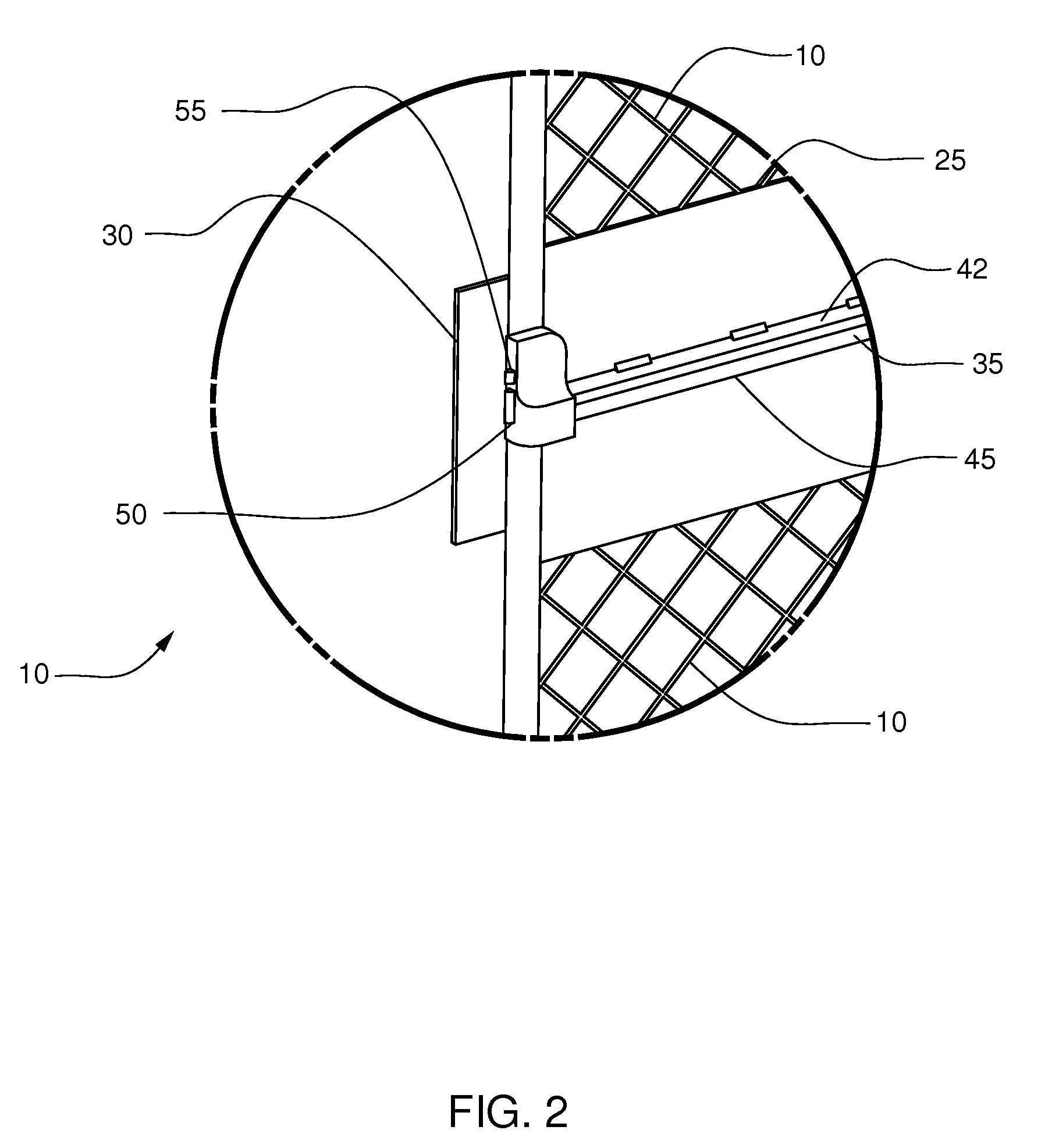
"The present invention provides an improved exit in a fence or gate that includes a door and a latch. The door is movable between a closed position and an open position, and the latch is operable to secure the door in the closed position. A guard is attached to one of the enclosure portions and projects inwardly proximate the latch to block attempts to reach the latch from outside the gate or fence. The invention also includes a reinforcement barrier on the door to prevent damage to the latch. The invention further includes methods for integrating the enclosure portions with the fence or gate, and for joining the enclosure portions together. Overall, the invention provides increased security and ease of installation for exits in fences and gates."

Problems solved by technology

Current gates are deficient in several ways.
Problems include lack of safety and difficulties surrounding the process of installing the gate.
Even though the work area is surrounded with a fence topped with barbed wire, terrorists could defeat current gates with little difficulty and cause a dramatic explosion.
However, because the pump jack is slippery with oil, they fall off and onto the underlying counterweight.
If they do not immediately hop off the counterweight, they can be crushed between the moving pump jack and the counterweight.
In spite of the identified risks posed by terrorist and to neighboring children, no progress has been made in improving exit-only gates and deterring unwanted access.
Therefore, the current practice is very time-consuming, with delays for obtaining a “hot-work” permit and for assembling the team to oversee this potentially disastrous activity.
The current practice is very expensive, with specialized employees necessary to prepare the permit application and to supervise the gate site.
Not to be ignored is the cost of closing down the work site: stopping oil pumping for several hours or a day can cost $10,000 to $100,000.
In contrast, there have been recent developments in child-proofing fences and gates, but most of these are designed to increase the difficulty of manipulating the gate and latches.
Such controls would slow employee exit and would not prevent terrorist access.
Clearly such mechanisms are incompatible with panic exiting from a gas or oil disaster.

Method used


Image

  • Panic Exit and Enclosure Gate Method
  • Panic Exit and Enclosure Gate Method
  • Panic Exit and Enclosure Gate Method

Examples


Embodiment Construction

[0030]There are significant problems and delays at oil and gas sites in installing the current style of panic-exit gates. Because of the current design, there are frequent reports of accidents and even deaths of children at oil and gas sites. Even worse, such sites could easily be entered by terrorists to create a large-scale incident. We have designed an innovative latched gate to solve these vexing safety problems. In an additional embodiment, we have made further improvements to not only increase safety but also avoid the risk of explosion during installation. Because of these additional improvements, companies can avoid welding and the attendant “hot-work” permitting process, closure of the work site and presence of additional personnel.

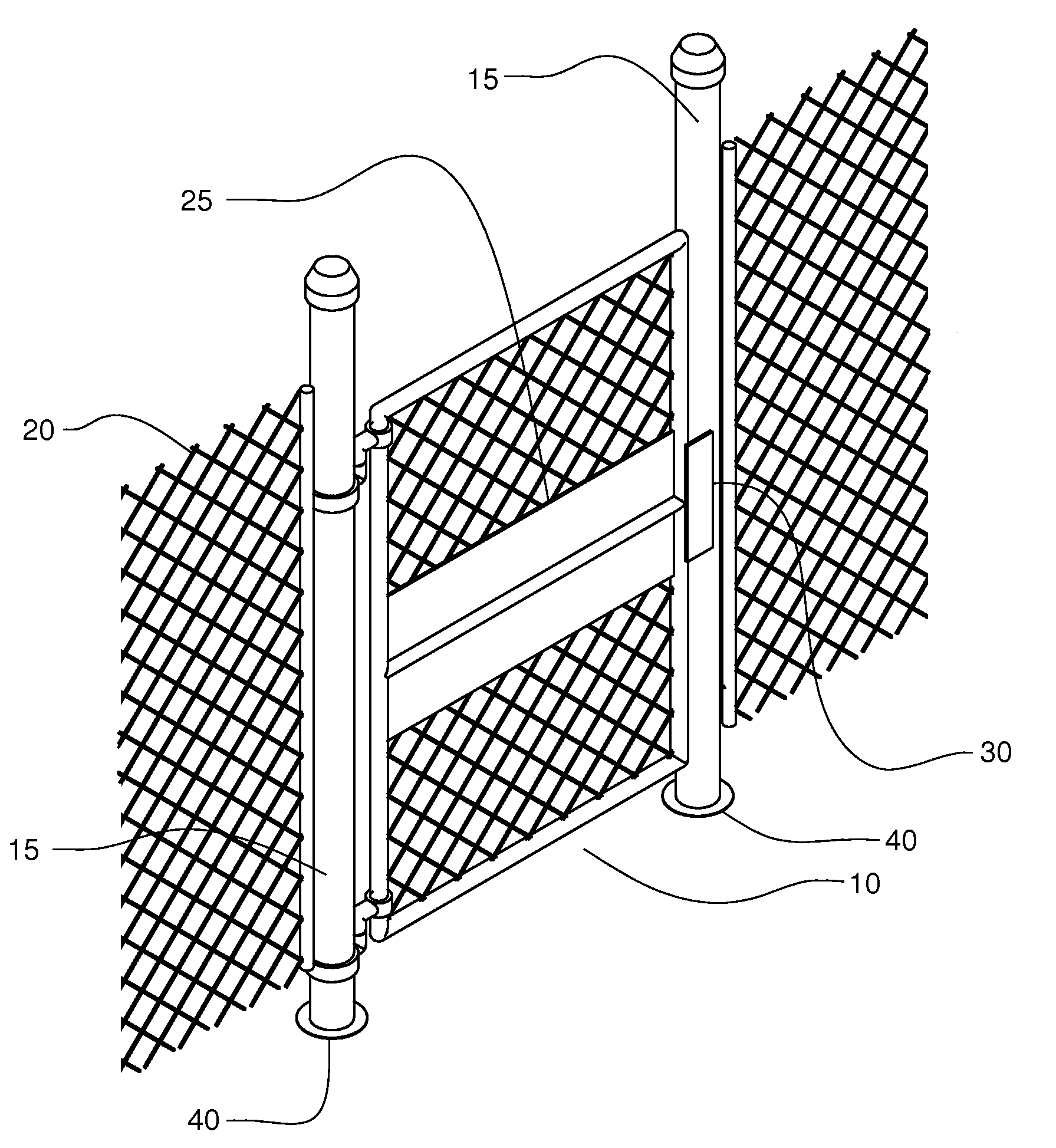
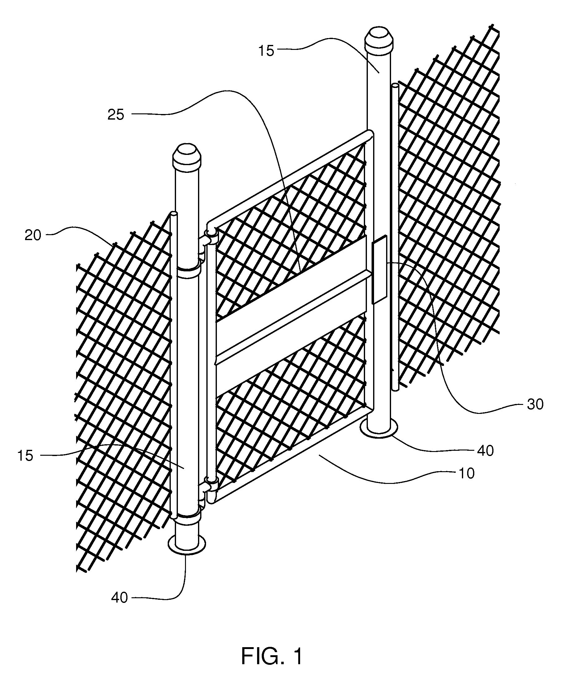
[0031]FIG. 1 shows an outside perspective view (from outside the work site) of current gate construction, which provides a light-weight chain-link gate 10, with light-weight supports 15 on either side which are welded to the chain-link fence 20. ...


PUM


Abstract

A method of gating a fence starts with providing an exit that has spaced-apart first and second enclosure portions joined by upper and lower cross-members and at least one anchor joined to at least one of said enclosure portions; a mostly solid door between said enclosure portions and openable, said door and said enclosure portions having inward-facing surfaces; a latch coupling said door to one enclosure portion, said latch securing said door closed, said latch only operable from said inward-facing surface; and a guard attached to one of said enclosure portions and projecting inwardly proximate said latch. The next steps are digging holes for the enclosure portions and at least one anchor sufficiently deep to permit the lower cross-member to sit in the ground; placing the exit; pouring concrete up to about the ground surface; and attaching the fence to the enclosure portions.

Description

RELATED APPLICATIONS[0001]This application claims the benefit of earlier-filed U.S. Provisional Patent Application No. 60 / 973,160, filed Sep. 17, 2007.TECHNICAL FIELD[0002]The present invention relates to safety exit gates designed to thwart entry by unwanted visitors and especially to such gates affording quick escape from fire or the like.BACKGROUND[0003]Oil and gas sites need to have exit-only doors for employees to race out if there is an explosion, spill or other serious problem. Generally, such exit-only gates are constructed on-site. The fence installer digs post holes for supports on either side of the gate. The supports are set in place and concrete is poured around the supports up to the ground level. Then connectors are welded to the supports to provide hinges for the door to swing open. For panic exits, the side of the gate facing the work area is equipped with a horizontal bar that immediately opens the gate when depressed.[0004]Current gates are deficient in several wa...

Claims


Application Information

Patent Timeline
Patent Type & Authority Applications(United States)
IPC IPC(8): E05C19/00E04H17/00
CPCE05B65/1046E05B65/0007Y10T292/0928Y10T292/79
Inventor GARLINGTON, MICHAEL JEREMYJANTZ, TIMOTHY RAY
Owner JANGAR MFG COMPANY
Learn More