
Injection Device of an Injection Molding Machine and Method for the Operation Thereof

a technology of injection molding machine and injection device, which is applied in the direction of auxillary shaping apparatus, manufacturing tools, ceramic shaping apparatus, etc., can solve the problem of material shrinkage and achieve the effect of high cos

Inactive Publication Date: 2009-03-12
SIEMENS AG
View PDF5 Cites 3 Cited by
  • Summary
  • Abstract
  • Description
  • Claims
  • Application Information

AI Technical Summary

Benefits of technology

[0008]The dynamic pressure and / or injection pressure are generally measured by pressure sensors. These can be sensors which directly measure the melt pressure in the screw antechamber or even strain gages or more specifically load cells which measure the bearing forces resulting from the dynamic pressure at a suitable place in the mechanism. Both methods involve high costs.
[0009]An object of the present invention is now to specify a method for operating an injection device of an injection molding machine or an injection device itself, whereby it is possible to eliminate hitherto necessary pressure sensors or corresponding measuring devices for determining the injection pressure or the dynamic pressure.
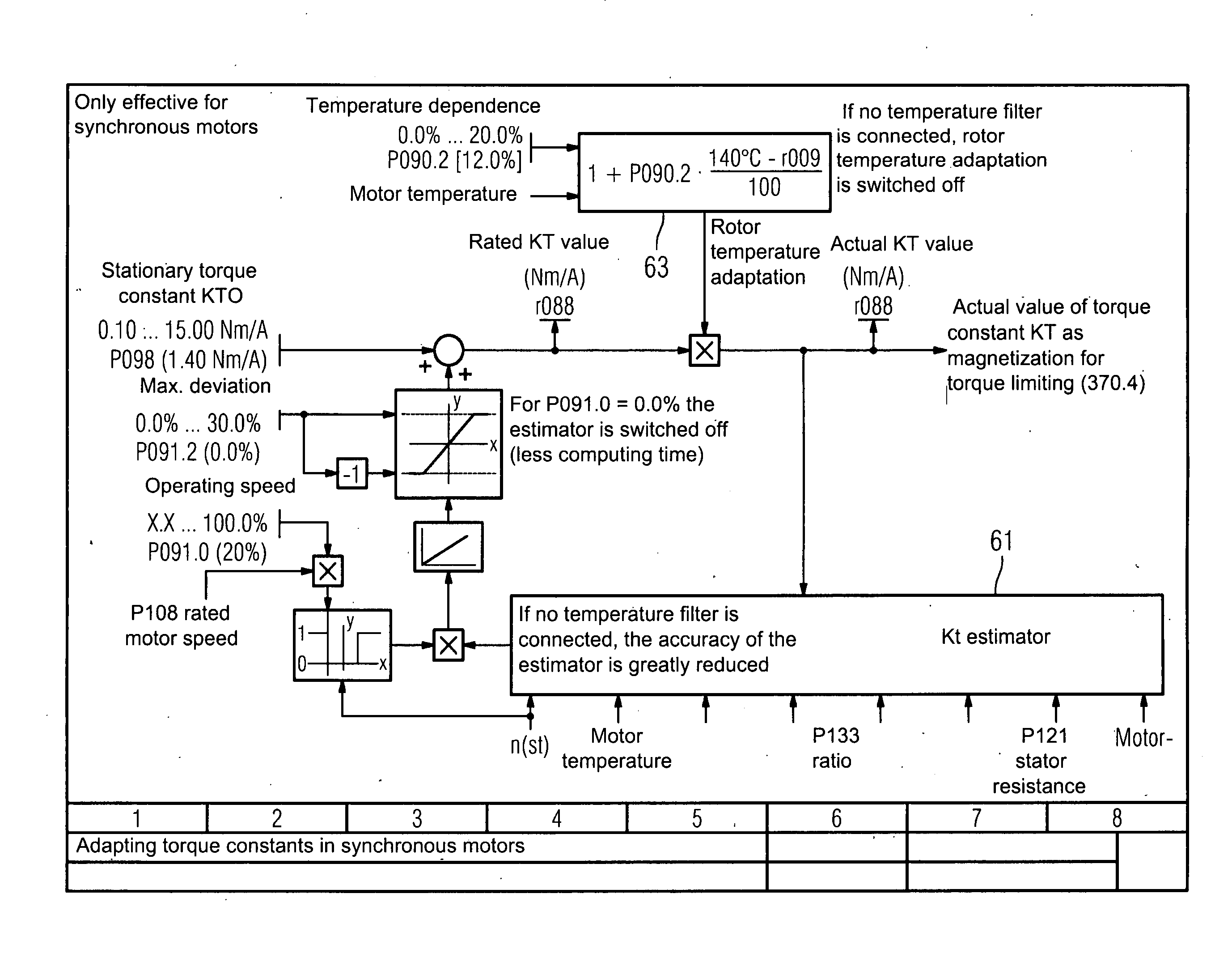
[0022]In another advantageous embodiment of the method, different values of the temperature dependent torque constant as a function of a temperature are used for calculating the injection pressure and / or dynamic pressure. By allowing for the temperature dependence of the Kt factor, i.e. the Kt value, the accuracy of the pressure calculation can be increased. Thus the dependence of the KT factor on the temperature of the magnetic material in the case of an electrical machine implemented as a permanent magnet excited electrical machine can additionally be compensated by measuring the motor temperature. When using commercially available neodymium-iron-boron permanent magnets, the decrease in the magnetization is typically 12% for 100 K heating of a rotor of the electrical machine.

Problems solved by technology

When the tool is now filled with injected material, the cooling of the material causes the material to shrink.

Method used


Image

  • Injection Device of an Injection Molding Machine and Method for the Operation Thereof
  • Injection Device of an Injection Molding Machine and Method for the Operation Thereof
  • Injection Device of an Injection Molding Machine and Method for the Operation Thereof

Examples


Embodiment Construction

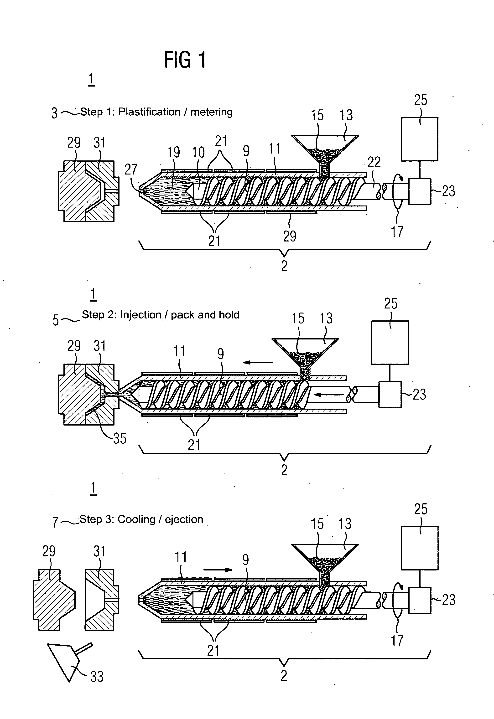
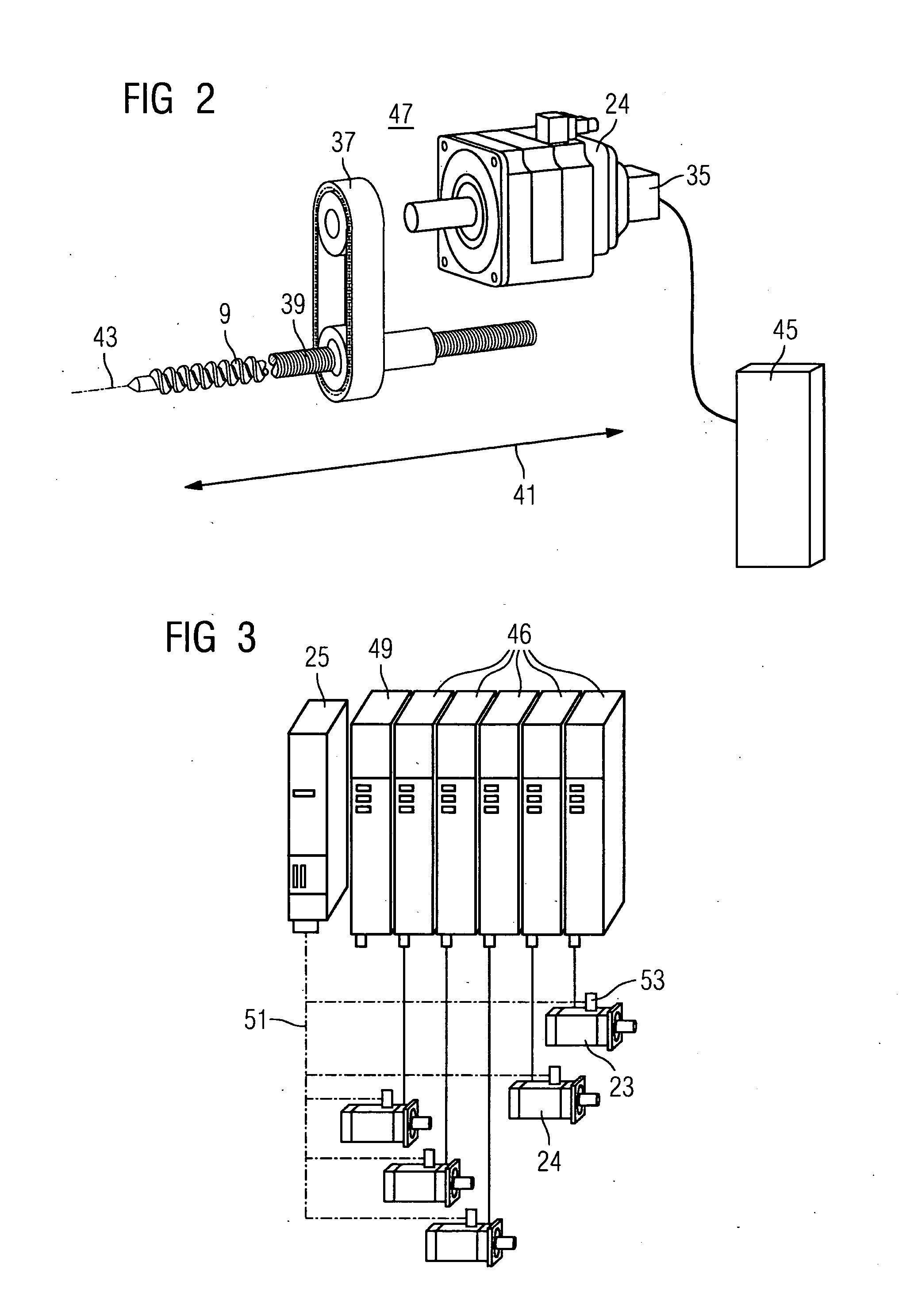
[0036]The drawing in FIG. 1 shows three steps 3, 5, 7 of an injection molding process (molding process) for an injection molding machine 1, illustrated in rudimentary fashion only, which has an injection device 2. The first step 3 relates to plasticization and metering, the second step 5 relates to injection and pack / hold and the third step 7 relates to cooling and ejection. The molding process relates to an injection molding machine 1. The injection molding machine 1 has a screw 9. The screw 9 is located in a screw cylinder 11. The injection molding machine 1 also has a hopper 13. The hopper 13 can be filled with plastic granulate 15. The plastic granulate 15 is to be transported into a screw antechamber by rotary motion 17 of the screw 9. During transportation, the plastic granulate is heated by friction or by means of an electric heater 21 to produce a melt. Rotary motion 17 causes the melt to accumulate in the screw antechamber 19 in front of the screw tip 10. The rotary motion ...


PUM

PropertyMeasurementUnit
timeaaaaaaaaaa
pressureaaaaaaaaaa
dynamic pressureaaaaaaaaaa

Abstract

There is described a device and a method for operating an injection device for an injection molding machine which is provided with an extruder screw that is driven by an electric machine. Acceleration values and / or values depending on an operating point of the electric machine are used for calculating an injection pressure and / or a ram pressure, thus dispensing with the need for a pressure sensor.

Description

CROSS REFERENCE TO RELATED APPLICATIONS[0001]This application is the US National Stage of International Application No. PCT / EP2006 / 070160, filed Dec. 22, 2006 and claims the benefit thereof. The International Application claims the benefits of German application No. 10 2006 001 346.8 DE filed Jan. 9, 2006, both of the applications are incorporated by reference herein in their entirety.FIELD OF INVENTION[0002]The invention relates to a method for operating an injection device of an injection molding machine and to a corresponding injection device. The injection molding machine has an injection device, said injection device comprising an extruder screw drivable by means of an electrical machine, a screw cylinder and a heater.BACKGROUND OF INVENTION[0003]A typical injection sequence will now be described. In an injection molding process, plastic granulate is fed via a fill hopper to a screw which is also known as an extruder screw. Rotary motion of the screw causes the plastic granulat...

Claims


Application Information

Patent Timeline
Patent Type & Authority Applications(United States)
IPC IPC(8): B29C45/77
CPCB29C45/77B29C2045/1792B29C2945/76023B29C2945/76033B29C2945/76173B29C2945/76214B29C2945/76986B29C2945/76498B29C2945/76735B29C2945/76859B29C2945/76862B29C2945/76939B29C2945/76381B29C2945/76003
Inventor BUDDE, THOMASGEIER, INGOOBERNDORFER, KLAUS
Owner SIEMENS AG
Learn More