
Pass-through grounding plug

a grounding plug and pass-through technology, applied in the direction of coupling devices, two-part coupling devices, electrical equipment, etc., can solve the problems of increasing the cost and space requirements of installing optical network terminals

Inactive Publication Date: 2009-03-05
ALCATEL-LUCENT USA INC
View PDF8 Cites 8 Cited by
  • Summary
  • Abstract
  • Description
  • Claims
  • Application Information

AI Technical Summary

Benefits of technology

"The present invention provides an electrical connector and a method of use thereof with an Optical Network Terminal. The electrical connector has a body with electrically-insulated material and includes a first electrically-conductive lead, a second electrically-conductive lead, and an electrically-conductive grounding prong. The grounding prong is at least one of retractable, removable from, and foldable into the body of the electrical connector. The Optical Network System includes an Optical Network Terminal and a power supply unit that provides power to the Optical Network Terminal, the power supply unit including an electrical connector with a grounding prong. The method for installing an Optical Network Terminal involves determining the distance between the installation location and the power source, and connecting the power supply unit directly to the power source when the power source includes a ground conductor and is within the predetermined distance. The technical effects of the invention include improved electrical connection and reliable power supply for Optical Network Terminals."

Problems solved by technology

However, since there is no ground connection to the Optical Network Terminal from the existing electrical infrastructure (such as a house mains), a separate ground must again be run from a ground rod (or similar grounded location) to the board of the Optical Network Terminal.
Providing the 3-wire cordset thus may increase the costs as well as space requirements associated with installation of the Optical Network Terminal.

Method used


Image

  • Pass-through grounding plug
  • Pass-through grounding plug
  • Pass-through grounding plug

Examples


Embodiment Construction

[0030]Reference will now be made in detail to the exemplary embodiments of the present invention, examples of which are illustrated in the accompanying drawings, wherein like reference numerals refer to like elements throughout.

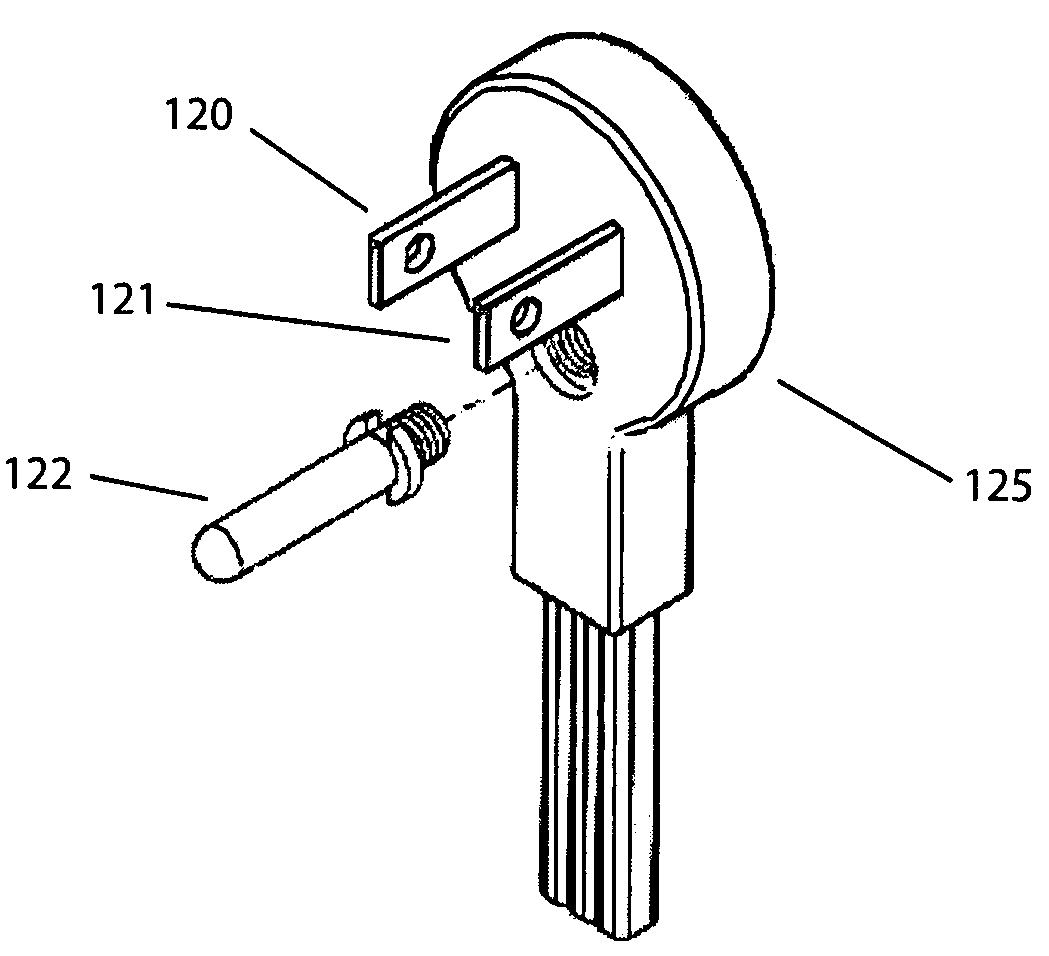
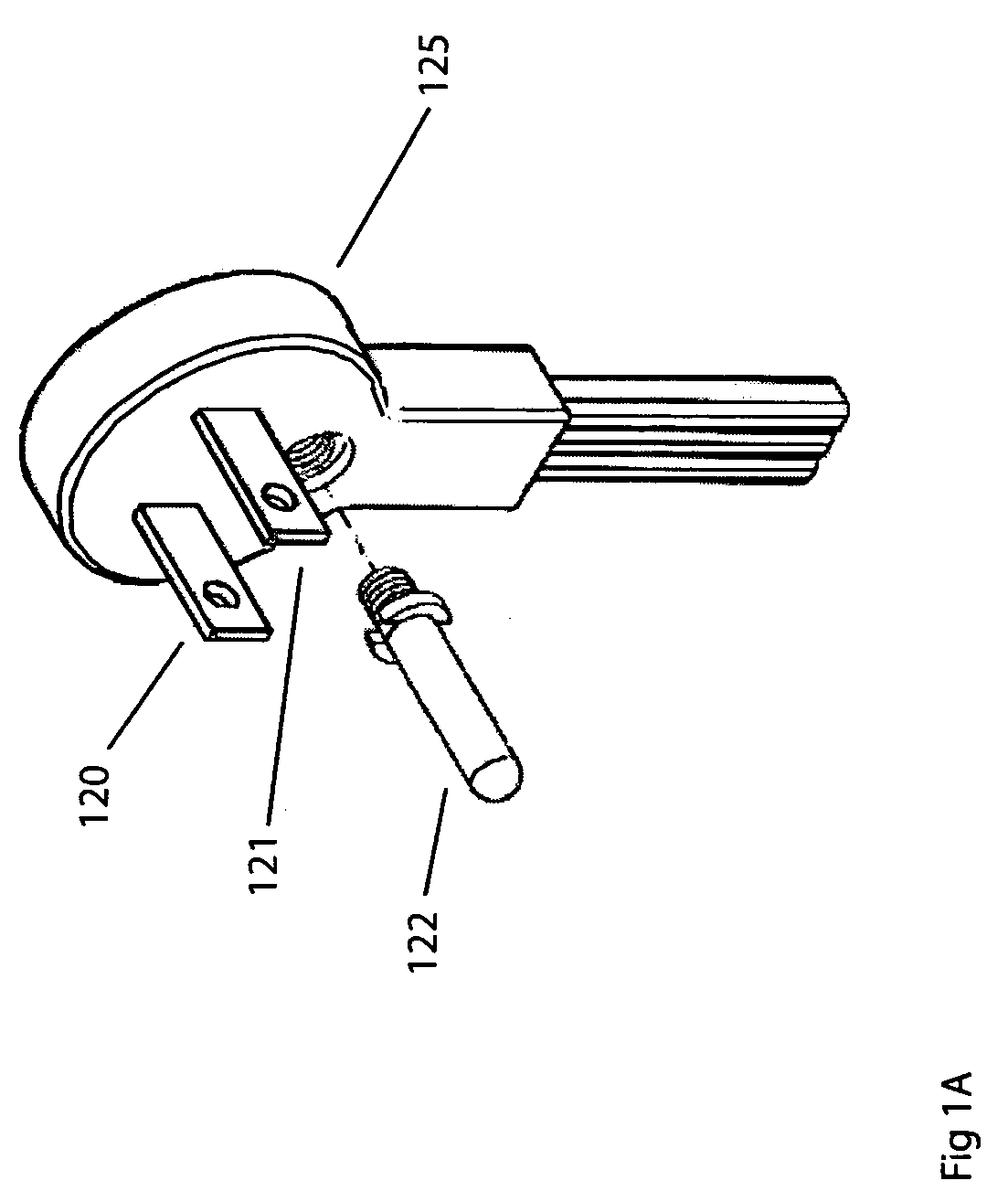
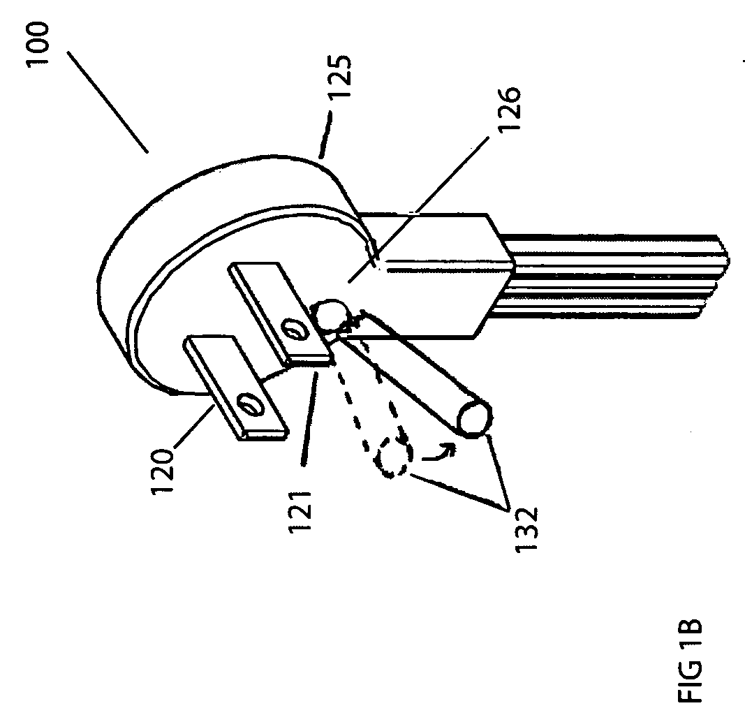
[0031]FIG. 1A illustrates an electrical connector 100 according to an exemplary embodiment of the present invention. As shown in FIG. 1A, the electrical connector 100 includes a body 125. The body 125 of the electrical connector 100 may include electrically-insulated material, such as an insulative thermoplastic elastomer (TPE) material.

[0032]The electrical connector 100 may also include a first electrically-conductive lead 120 secured in the body 125 and extending therefrom. The first electrically-conductive lead 120 may be operable to engage a hot conductor of an electrical component (not shown). Further, a second electrically-conductive lead 121 may be secured in the body 125 of the electrical connector 100 and extending therefrom. The second lead 121 may ...


PUM


Abstract

An electrical connector and a method of use of the electrical connector during installation of an Optical Network Terminal (ONT). The ONT includes a power supply unit having a pass-through grounding plug. The pass-through grounding plug includes an electrically-conductive grounding prong that is operable to engage a ground conductor of an electrical component. For installation purposes, for example, using existing home wiring, the grounding prong may be retractable, removable and foldable into a body of the plug. When installing the ONT, one would determine whether a power source to which a power supply unit of the ONT is to be connected is within a predetermined distance from an installation location of the ONT. Further, one would determine whether the power source includes a ground conductor. In instances where there is not a ground conductor, the grounding prong may be removed, folded, or retracted into the body of the plug.

Description

CROSS-REFERENCE TO RELATED APPLICATIONS[0001]This application claims priority to U.S. Provisional Application No. 60 / 939,122, filed on May 21, 2007, the disclosure of which is incorporated herein in its entirety by reference.BACKGROUND OF THE INVENTION[0002]1. Field of the Invention[0003]Methods and apparatuses consistent with the present invention relate to an electrical connector and a method of use thereof during installation of an Optical Network Terminal. More particularly, the electrical connector may be a pass-through grounding plug used with a power supply of the Optical Network Terminal, wherein the pass-through grounding plug includes at least one of a removable, retractable, folding, or breakaway grounding prong to facilitate installation of the Optical Network Terminal.[0004]2. Description of the Related Art[0005]An Optical Network System distributes an optical signal from, for example, a central office over an optical distribution network. At the endpoints of this netwo...

Claims


Application Information

Patent Timeline
Patent Type & Authority Applications(United States)
IPC IPC(8): H01R29/00
CPCH01R2103/00H01R24/30
Inventor POWELL, BRUCE DOUGLASNOTO, ANTHONY P.
Owner ALCATEL-LUCENT USA INC
Learn More