
Storage apparatus and data managament method

Active Publication Date: 2009-03-05
HITACHI LTD
View PDF4 Cites 10 Cited by
  • Summary
  • Abstract
  • Description
  • Claims
  • Application Information

AI Technical Summary

Benefits of technology

[0019]According to the above aspects of this invention, data can be remote-copied with ensured data security and high system performance.
[0020]In addition, according to the above aspects of this invention, if an encryption key for a logical volume storing data has been updated, data encrypted with the up-to-date encryption key can be efficiently stored in the logical volume, and the encrypted data can be efficiently read from the logical volume and decrypted.

Problems solved by technology

However, in old encrypted data that has been kept for a long time after the encryption, the encryption key and encryption algorithm used in the encryption might be weakened.
In terms of data security, when data is encrypted or re-encrypted, since encryption / re-encryption processing applies a large load on a processor, system performance deteriorates.
Under such circumstances, a storage system that performs encryption / re-encryption causing a large processing load during remote copy has not been proposed.

Method used


Image

  • Storage apparatus and data managament method
  • Storage apparatus and data managament method
  • Storage apparatus and data managament method

Examples


first embodiment

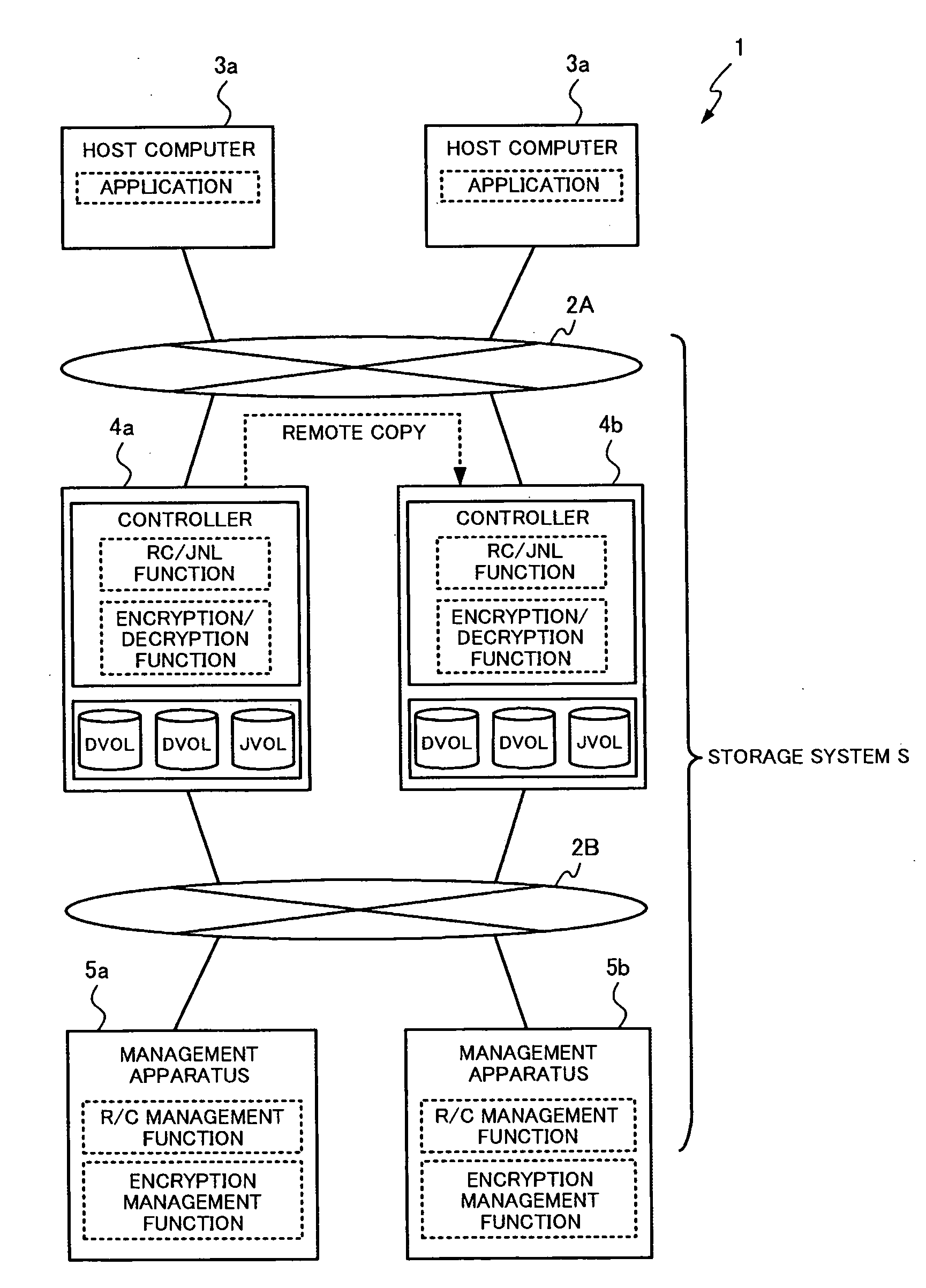
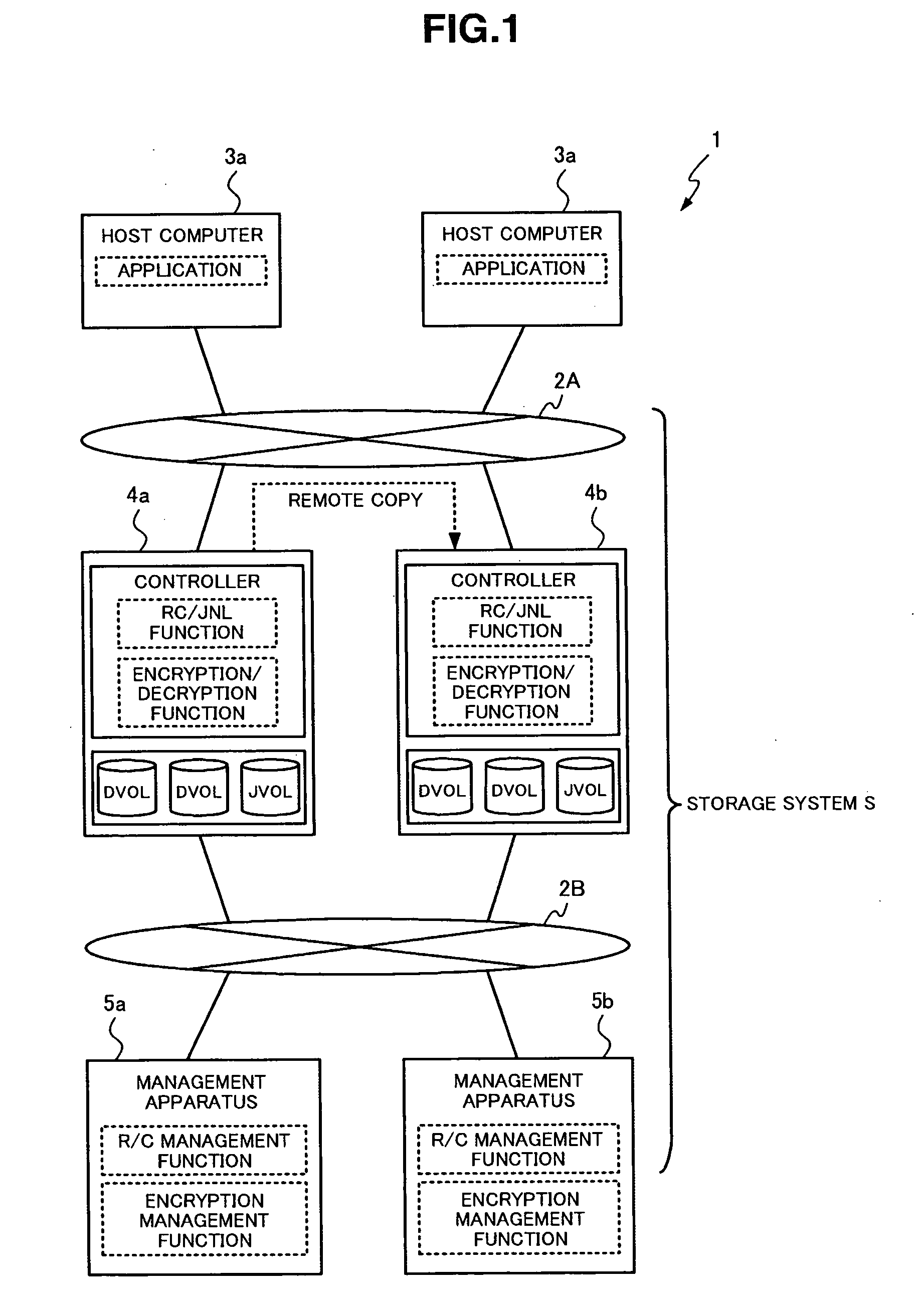
[0049]FIG. 1 is a diagram schematically showing the structure of a computer system according to an embodiment of this invention. As shown in FIG. 1, a computer system 1 includes a plurality of host computers 3 and a plurality of storage apparatuses 4 that are operatively connected to each other via a storage network 2A. The plurality of storage apparatuses 4 may also be regarded as one storage system S. The computer system 1 also includes management apparatuses 5 respectively operatively connected to each of the plurality of storage apparatuses 4 via a management network 2B. The computer 1 can be embodied in main systems for banks, seat reservation systems for airlines, etc.

[0050]The storage network 2A is a network system mainly used for communication based on I / O accesses between the host computers 3 and the storage apparatuses 4. The storage network 2A is also used for communication based on remote copy between storage apparatuses 4. The storage network 2A may be any of a LAN, the...

second embodiment

[0161]This embodiment has a feature in which a switch control command is written in a journal volume storage area indicated by a journal end pointer, instead of providing a switch pointer managed by the encryption key update management table, to switch a storage-destination for journals to a storage area in a new journal volume. The description below mainly describe differences from the embodiment

[0162]FIG. 17 is a flowchart for explaining encryption key update processing in the storage apparatus 4 according to the embodiment of this invention. Specifically, FIG. 17 explains the operation of the storage apparatus 4a when the storage apparatus 4a receives an encryption key update command from the management apparatus 5a.

[0163]A system administrator operates the management apparatus 5a to command the storage apparatus 4a to update an encryption key, and the management apparatus 5a transmits an encryption key update command to the storage apparatus 4a. The encryption key update comman...

third embodiment

[0177]This embodiment provides a mechanism for storing journals continuously in an existing journal volume without securing a new journal volume when an encryption key is updated.

[0178]FIG. 20 is a diagram for explaining the structure of an encryption key update management table T400′ in the storage apparatus 4 according to the embodiment of this invention.

[0179]As shown in FIG. 20, the encryption key update management table T400′ in this embodiment includes the journal volume identifier field T401, the encryption key update status field T402, the switch pointer filed T403, an old encryption status field T404 and an old encryption key field T405. Compared with the encryption key update management table T400 shown in FIG. 7, the old encryption status field T404 and the old encryption key field T405 are additionally provided.

[0180]Entered in the old encryption status field T404 is the encryption status of a journal volume specified by an encryption key update command before the recept...


PUM


Abstract

Provided is a storage system that includes a first storage apparatus and a second storage apparatus each connected to a host computer. The first and second storage apparatuses each include a controller and a disk drive. The controller manages an encryption status and an encryption key for each of a data volume and a journal volume in the disk drive. The controller in the first storage apparatus receives a write request from the host computer, creates a journal based on write data, encrypts the journal, and stores in an order the journal in a storage area in the journal volume. The controller in the order the encrypted journal stored in the journal volume, decrypts the journal, and transmits the decrypted journal to the second storage apparatus.

Description

CROSS-REFERENCES TO RELATED APPLICATIONS[0001]This application relates to and claims priority from Japanese Patent Application No. JP2007-230537, filed on Sep. 5, 2007, the entire disclosure of which is incorporated herein by reference.BACKGROUND[0002]1. Field of the Invention[0003]The invention relates generally to a storage apparatus and method of managing storage data using the same, and particularly to a remote copy technique for storage data using a journal between storage apparatuses having data encryption / decryption functions.[0004]2. Description of Related Art[0005]In order to prevent data loss caused by failures that occur in a storage apparatus in a computer system, data stored in a logical volume in the storage apparatus is normally backed up in another logical volume in a remote storage apparatus that is redundantly structured. For example, “remote copy” (or “remote mirroring”) is known as a technique for backing up data in logical volumes. Specifically, in the remote co...

Claims


Application Information

Patent Timeline
IPC IPC(8): H04L9/00G06F21/60G06F21/62G06F21/80
CPCG06F11/2074G06F21/6218H04L9/0891H04L9/083G06F21/805
Inventor MIKAMI, KYOKOOSAKI, NOBUYUKI
Owner HITACHI LTD
Learn More