Center console structure of vehicle
a technology of center console and vehicle body, which is applied in the direction of refrigerated goods vehicles, transportation and packaging, transportation items, etc., can solve the problems of increased burden on batteries, loss of flow amount or heat of conditioning air flowing,
- Summary
- Abstract
- Description
- Claims
- Application Information
AI Technical Summary
Benefits of technology
Problems solved by technology
Method used
Image
Examples
embodiment 1
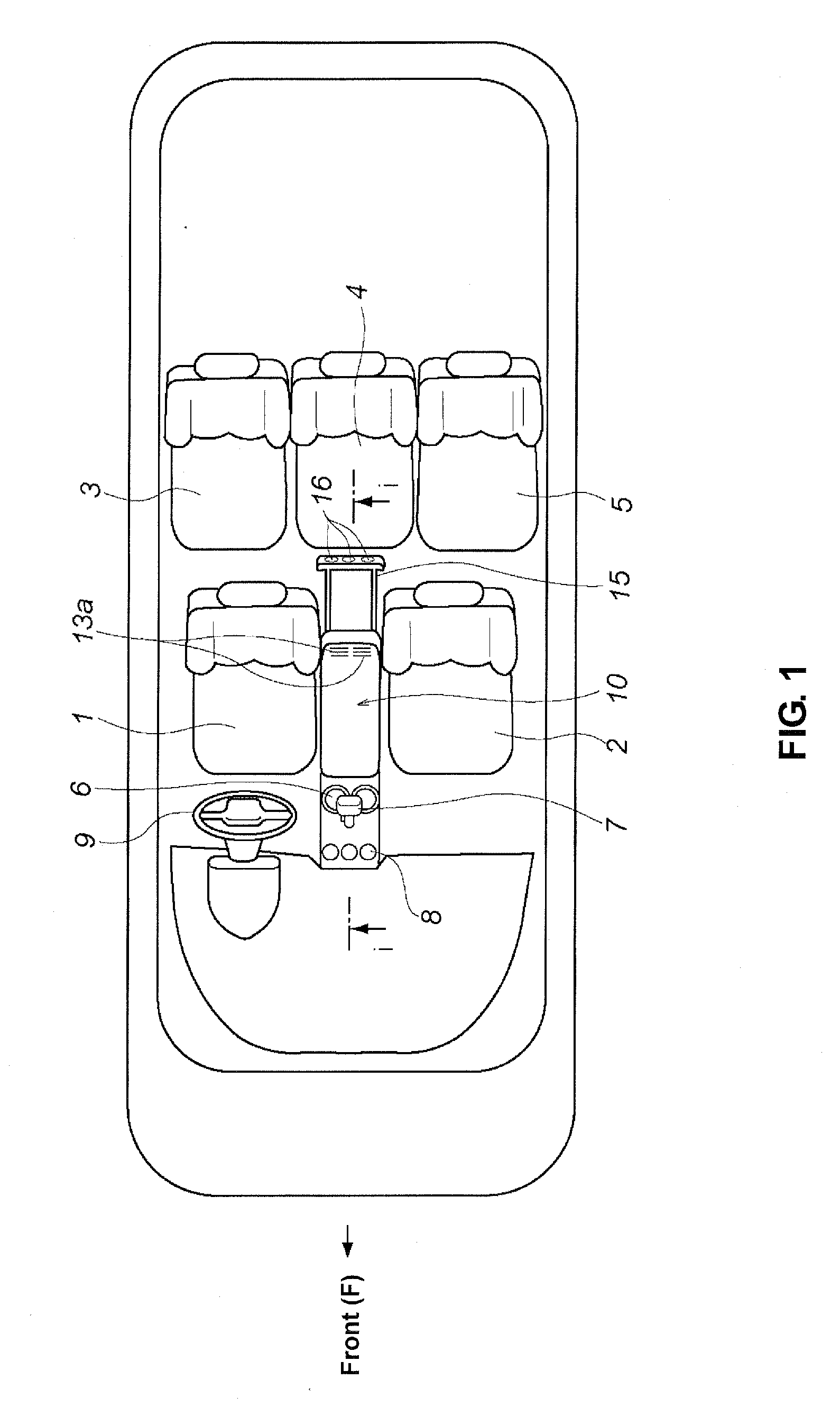
[0043]FIG. 1 is a schematic plan view of a vehicle compartment of a vehicle according to the present embodiment.
[0044]As shown in FIG. 1, a center console 10 is disposed between both-side front seats in the vehicle compartment, i.e., a driver's seat 1 and a passenger's seat 2. A cup holder 6 is provided in front of the center console 10. A shift lever 7 and an air-conditioning operational portion 8 for the front seats are disposed further before. A rear face of the center console 10 is located in front of a center rear seat 4. Beside the shift lever 7 is provided a steering wheel 9, a lower portion of which is located substantially at the same level as a knob of the shift lever 7.
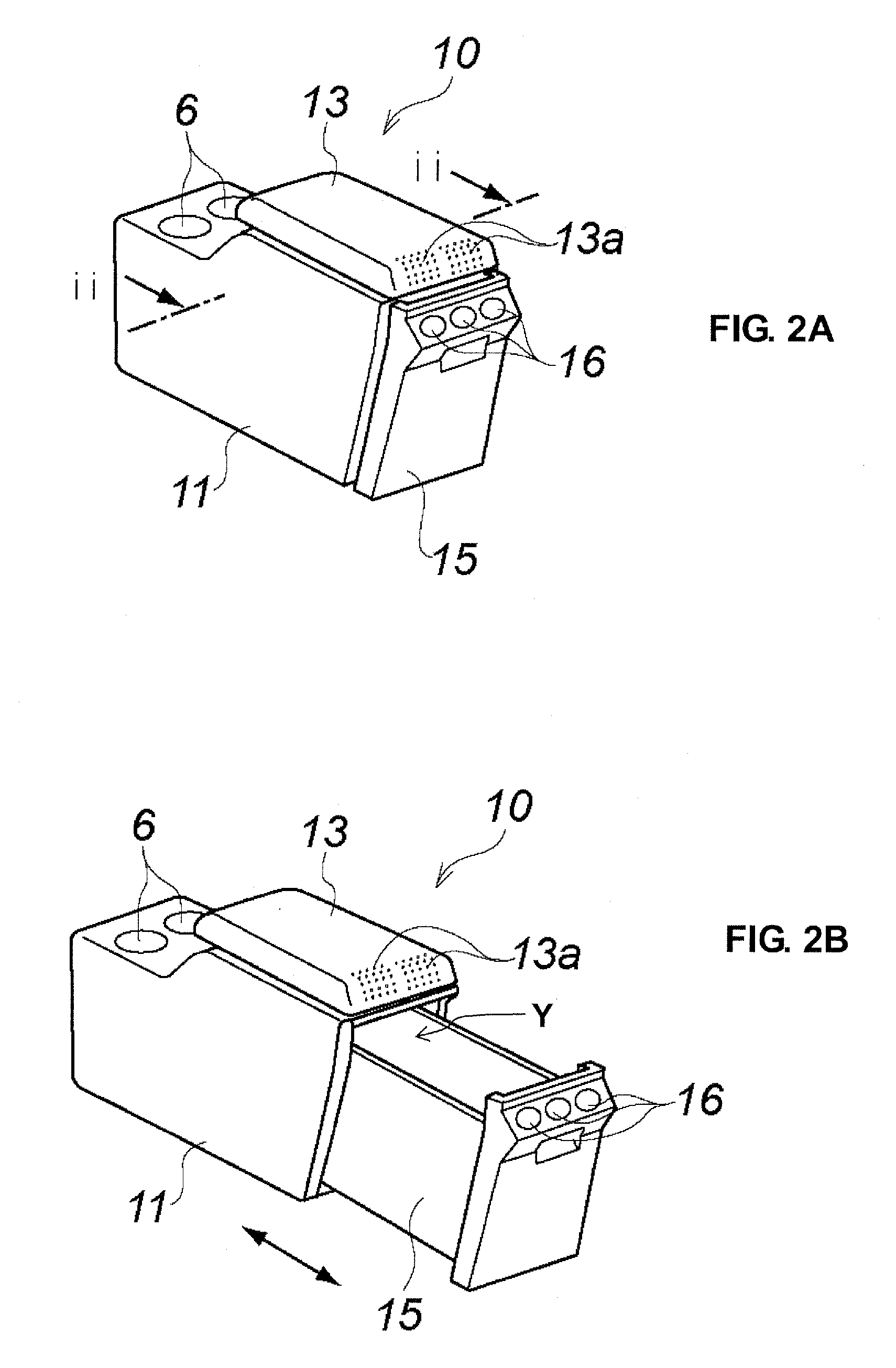
[0045]FIGS. 2A and 2B are perspective views showing a structure of the center console according to the present embodiment. FIG. 2A shows a state in which a storage box is stored, FIG. 2B shows a state in which the storage box is drawn out. FIG. 3 is a sectional view taken along line ii-ii of FIG. 2A. FIG. 4...
embodiment 2
[0056]Hereinafter, a center console stricture according to a second embodiment of the present invention will be described. The same structures as those of the above-described first embodiment will be denoted by the same reference characters, detailed descriptions of which are omitted here.
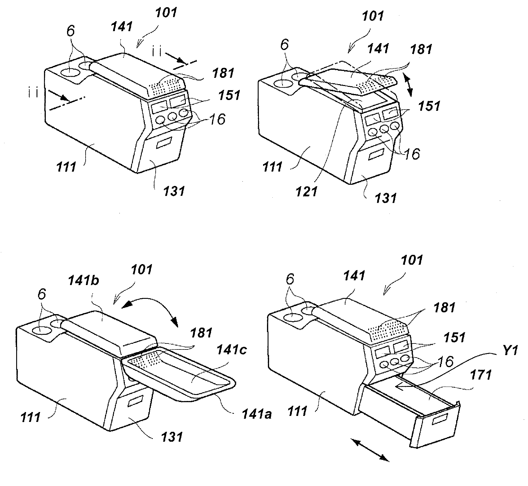
[0057]A center console 101 of the present embodiment is provided between the driver's seat 1 and the passenger's seat 2 likewise as shown in FIG. 6.
[0058]The center console 101, as shown in FIGS. 7-10, comprises a console body 111 which has the hollow box-shaped outer shape and extends in the vehicle longitudinal direction, an upper storage portion 121 which is provided inside the console body 111 and has an upper opening X1, a storage portion 131 which is provided below the upper storage portion 121 inside the console body 111 and has a rear opening Y1, and an armrest 141 which is supported at the console body 111 so as to open and close the upper opening X1 of the upper storage portion 121.
[0059]...
embodiment 3
[0070]FIG. 11 is a view showing a structure of a center console 102 according to a third embodiment of the present invention, which corresponds to a sectional view taken along line ii-ii of FIG. 7A. The same structures as those in FIG. 8 are denoted by the same reference characters.
[0071]The heat-exchanging portion is comprised of the through holes 221 in the above-described second embodiment. According to the present embodiment, however, an air-conditioning air duct 401 is made of a heat-conductive metal or resin, such as aluminum alloy, which is supported at shelves 411, and further at the duct 401 are provided plural fins 421 as the heat-exchanging portion. These fins 421 can increase a surface area of the duct 401 which exposes to the upper storage portion 121 and the storage portion 131.
PUM
 Abstract
Description
Claims
Application Information
 - R&D
- Intellectual Property
- Life Sciences
- Materials
- Tech Scout
- Unparalleled Data Quality
- Higher Quality Content
- 60% Fewer Hallucinations
Browse by: Latest US Patents, China's latest patents, Technical Efficacy Thesaurus, Application Domain, Technology Topic, Popular Technical Reports.
© 2025 PatSnap. All rights reserved.Legal|Privacy policy|Modern Slavery Act Transparency Statement|Sitemap|About US| Contact US: help@patsnap.com


