Lancing device

a technology of lancets and piercings, which is applied in the field of lancets, can solve the problems of piercing the skin of patients, possible premature firing of lancets, and safety risks, and achieve the effects of convenient use, low manufacturing cost, and compact construction

Inactive Publication Date: 2009-02-26
ABBOTT DIABETES CARE INC
View PDF32 Cites 66 Cited by
  • Summary
  • Abstract
  • Description
  • Claims
  • Application Information

AI Technical Summary

Benefits of technology

[0019]It is yet still another object of the present invention to provide a lancing device of the type described above which has a limited number of parts, which is inexpensive to manufacture and which is easy to use.

Problems solved by technology

In some lancet devices, the lancet extends from the body at all times. As can readily be appreciated, such lancet devices may inadvertently prick people and / or become contaminated with foreign objects and, therefore, pose a safety risk.
Typically, the movement of the lancet from its retracted position to its extended position is effected with such force that contact of the moving lancet tip with the skin of a patient results in the piercing of the skin of the patient.
One drawback associated with single-use lancet devices is that it is possible for the lancet to be fired prematurely simply by the inadvertent application of pressure to the lancet device.
As can readily be appreciated, the premature firing of the lancet may result in an undesired piercing of a person and / or in the contamination of the lancet.
One drawback associated with the aforementioned lancet device is that such a lancet device typically comprises a pair of linear springs, one of which is used to fire the lancet out from the protective body and into the skin of the patient and another which is used to retract the lancet back into the body after pricking the skin of the patient.
Accordingly, it has been found by lancet design engineers to be difficult to contain such a device into a relatively compact package, which is highly desirable.
However, it is also to be understood that the aforementioned device suffers from a few notable drawbacks.
As a first drawback, the aforementioned lancing device is of the pre-loaded variety, with the torsion spring originally configured in its pre-stressed, or cocked, state.
As a result, the lancet device is incapable of more than a single use, which is highly undesirable.
As a second drawback, the aforementioned lancing device is designed to cleave, and not prick, the skin of a patient.
The large incision created through the cleaving process can result in excessive patient bleeding and pain, which is highly undesirable.

Method used


Image

  • Lancing device
  • Lancing device
  • Lancing device

Examples


first embodiment

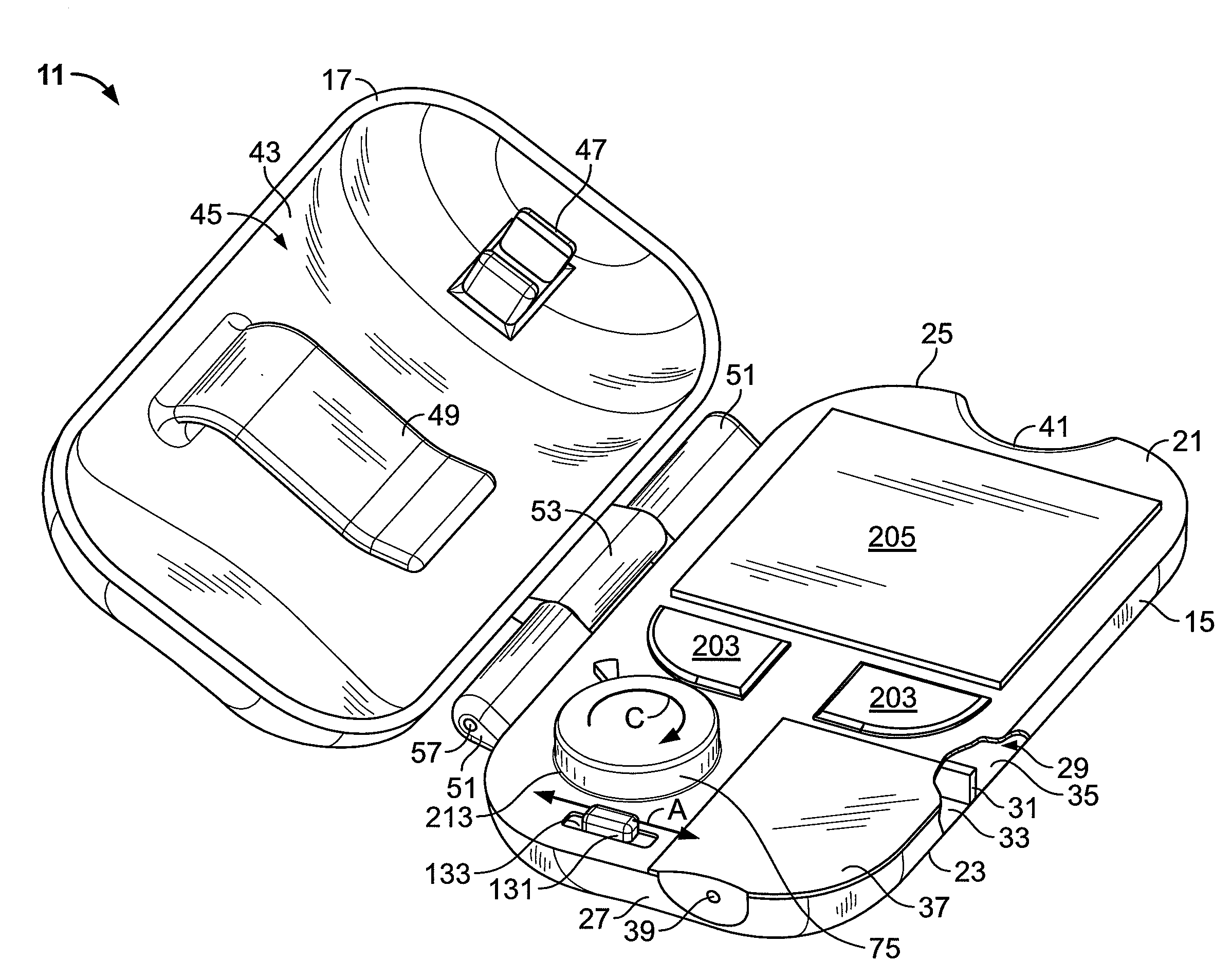
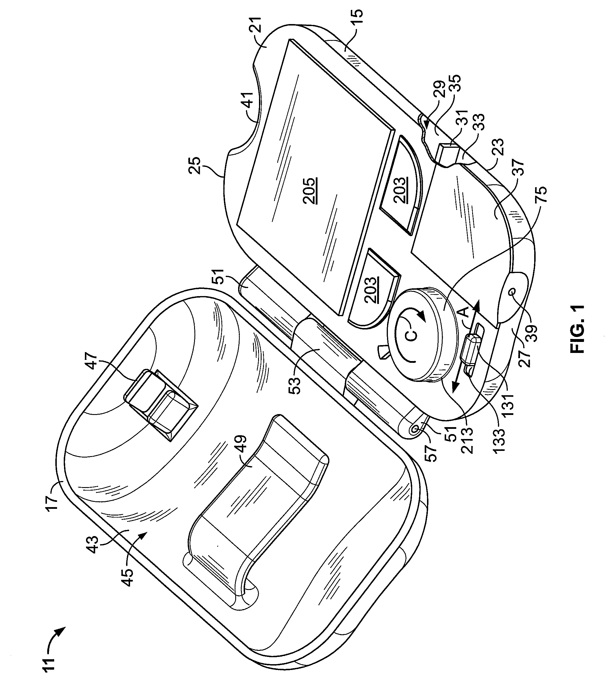
[0046]Referring now to the drawings, there is shown in FIGS. 1 and 2, a lancing device which is constructed according to the teachings of the present invention, the lancing device being identified generally by reference numeral 11. As will be described further below, selected components of lancing device 11 are used to fire a lancet into the skin of a patient to acquire a blood sample and selected components of lancing device are used to calculate and display the concentration of a particular analyte (e.g., glucose) in the acquired blood sample.

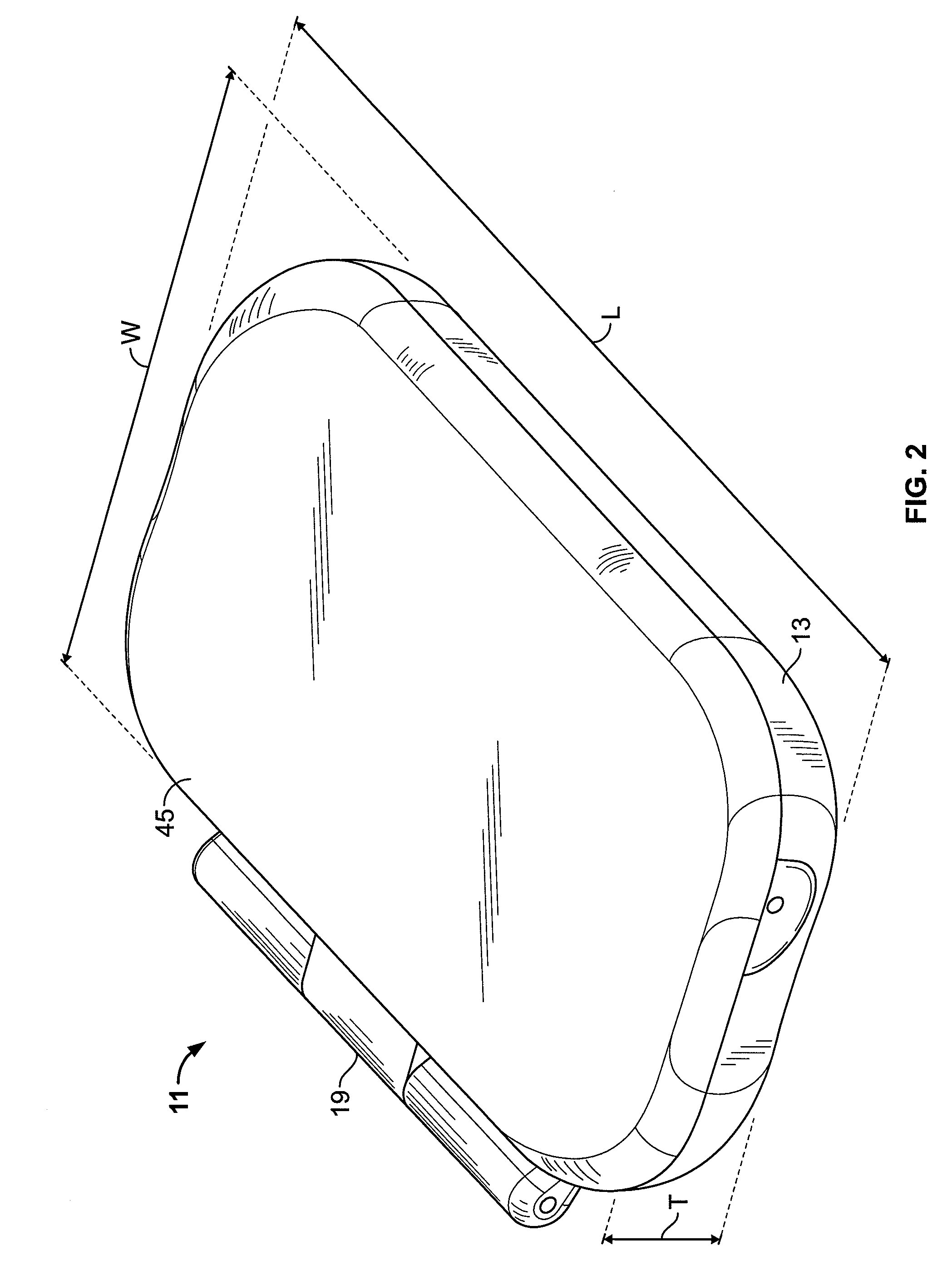
[0047]Lancing device 11 comprises a housing 13 constructed of a rigid and durable material, such as molded plastic. Housing 13 includes a base 15 and a cover 17 pivotally mounted to base 15 about a hinge 19. As such, cover 17 is capable of being pivoted between an open position, as shown in FIG. 1, and a closed position, as shown in FIG. 2. With cover 17 disposed in its closed position, as shown in FIG. 2, housing 13 has an overall length L o...

second embodiment

[0128]It should be noted that various modifications to the construction of lancing device 11 could be made without departing from the spirit of the present invention. As an example, referring now to FIGS. 18 and 19, there is shown a lancing device constructed according to the teachings of the present invention and identified generally by reference numeral 301.

[0129]Lancing device 301 differs from lancing device 11 in that lancing device 301 comprises a three component housing whereas lancing device 11 comprises a two component housing. Specifically, lancing device 301 comprises a base 303, a cover 305 and a partition 307 which are pivotally coupled together by a hinge 309.

[0130]Base 303 includes the identical internal components found in base 15 of lancing device 11. Base 303 differs principally from base 15 in that base 303 does not include a display. Because base 303 does not include a display, base 303 is capable of supporting a five button interface 311 rather than the two butto...


PUM


Abstract

A lancing device is adapted for use in firing a lancet into the skin of a patient to acquire a blood sample and, subsequent thereto, calculating and displaying the concentration of glucose in the acquired sample. In one embodiment, the device comprises a lancet and a torsion spring coupled to the lancet through a lancet holder. The torsion spring includes inner, middle and outer rings which are concentrically configured, a plurality of activation spring arms which connect the middle and outer rings and a plurality of return spring arms which connect the inner and middle rings. In use, the plurality of activation and return spring arms can be independently transformed between energized and de-energized states using a single, button-shaped mechanism. Rotation of the mechanism is used to energize the activation and return spring arms. With the return spring arms maintained in their energized state, depression of the mechanism transforms the activation spring arms from their energized state to their de-energized state which drives the lancet from a retracted position to an extended position. Once the activation spring arms reach their de-energized state, the return spring arms transform from their energized state to their de-energized state which pulls the lancet back from its extended position to its retracted position.

Description

BACKGROUND OF THE INVENTION[0001]The present invention relates generally to lancing devices and more particularly to a novel lancing device.[0002]Diabetes is a disease which typically requires a patient to routinely measure the concentration of glucose in his / her blood. Based upon the results of each blood glucose measurement, the patient may require a particular drug treatment (e.g., an injection of insulin) in order to regulate that the blood glucose level of the patient remains within a specified range. Exceeding the upper limit of said range (hyperglycemia) or dropping beneath the lower limit of said range (hypoglycemia) should be avoided with as much diligence as possible to prevent the patient from experiencing serious medical complications which include, inter alia, retinopathy, nephropathy, and neuropathy.[0003]A two-step process is commonly practiced by diabetes patients to self-monitor the level of glucose present in their blood. In the first step, the patient pricks his / h...

Claims


Application Information

Patent Timeline
IPC IPC(8): A61B5/151A61B17/32A61B5/00A61B5/15
CPCA61B5/14532A61B5/1411A61B5/150022A61B5/15019A61B5/150305A61B5/150358A61B5/150412A61B5/150847A61B5/15113A61B5/15117A61B5/1519A61B5/15194A61B5/157
Inventor MACE, CHAD HAROLD
Owner ABBOTT DIABETES CARE INC
Why Eureka
Try Eureka