
Underground irrigation system

a technology of irrigation system and irrigation system, which is applied in the direction of watering devices, soil drainage, construction, etc., can solve the problems of prone to breakdown of sprinkler heads, nozzles that are somewhat expensive, and conventional underground sprinkler systems incorporating sprinkler nozzles exhibit a number of problems, and achieve the effect of simple and inexpensiv

Inactive Publication Date: 2009-02-26
GREEN HYDROTEC
View PDF13 Cites 15 Cited by
  • Summary
  • Abstract
  • Description
  • Claims
  • Application Information

AI Technical Summary

Benefits of technology

[0008]It is an aspect of the present invention to provide simple and inexpensive apparatus for watering an area of soil.
[0009]It is also another aspect of the present invention to provide an improved underground irrigation system incorporating improved irrigation piping that is economical and can be installed at relatively low cost and with a minimum of digging.

Problems solved by technology

Conventional underground sprinkler systems incorporating sprinkler nozzles generally exhibit a number of problems.
The sprinkler heads are usually fabricated from a large number of parts which must be assembled thereby making the nozzles somewhat expensive since the manufacturing and assembling costs are quite high.
The large number of parts makes the sprinkler heads susceptible to breakdown increasing the amount of maintenance required for underground sprinkler systems.
Most underground sprinkler systems are difficult to partially disassemble when repairing a malfunctioning sprinkler head.
Still another drawback to conventional underground sprinkler systems, is the large amounts of water such systems tend to use.
These underground irrigation systems are often beset with the problem of blockage from debris in the irrigation water or from surrounding soil or build up of solids in the flow apertures.
Generally, high water pressures are required to keep their apertures open.
When the system is turned off the apertures are subject to clogging.

Method used


Image

  • Underground irrigation system
  • Underground irrigation system
  • Underground irrigation system

Examples


Embodiment Construction

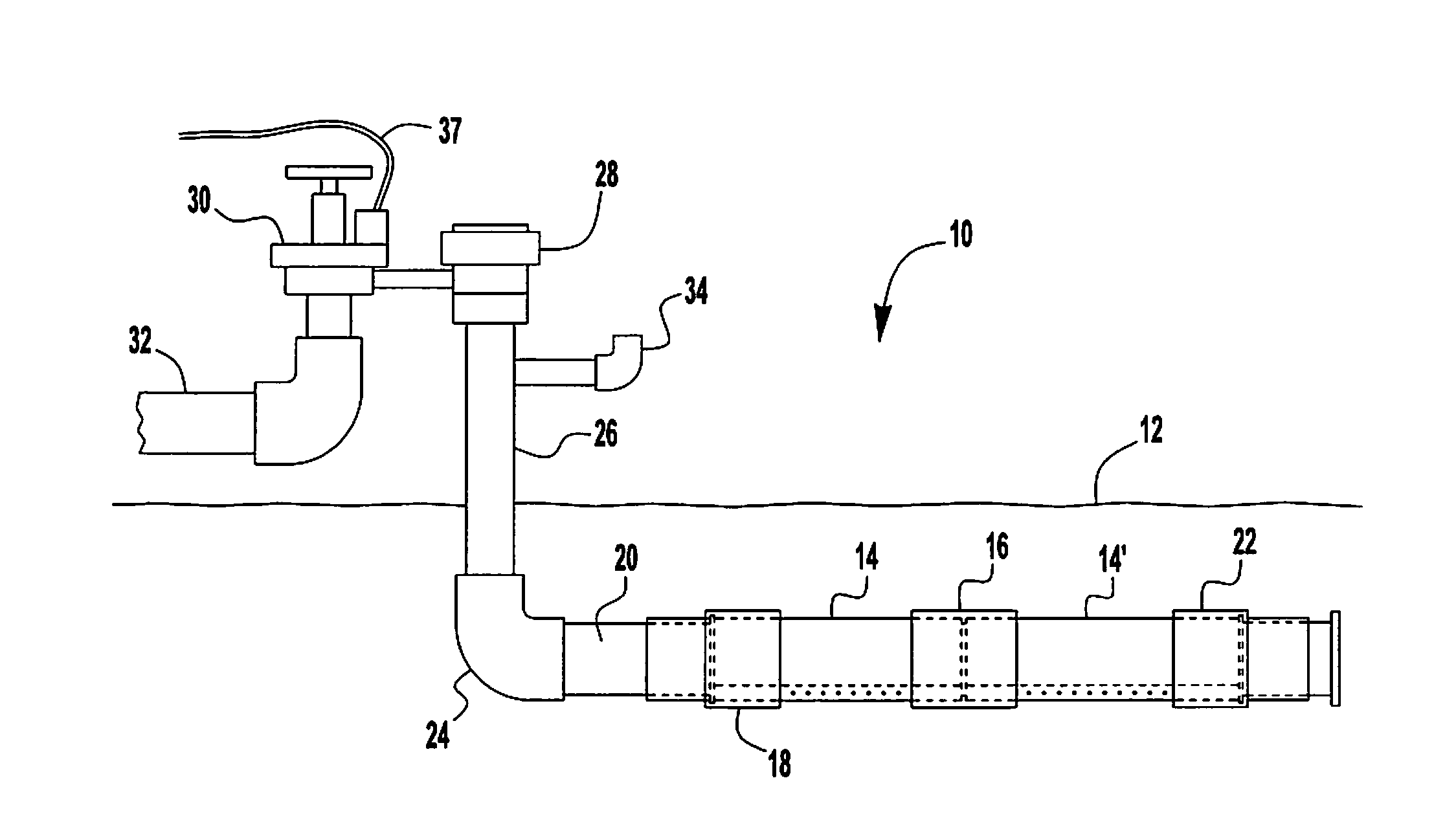
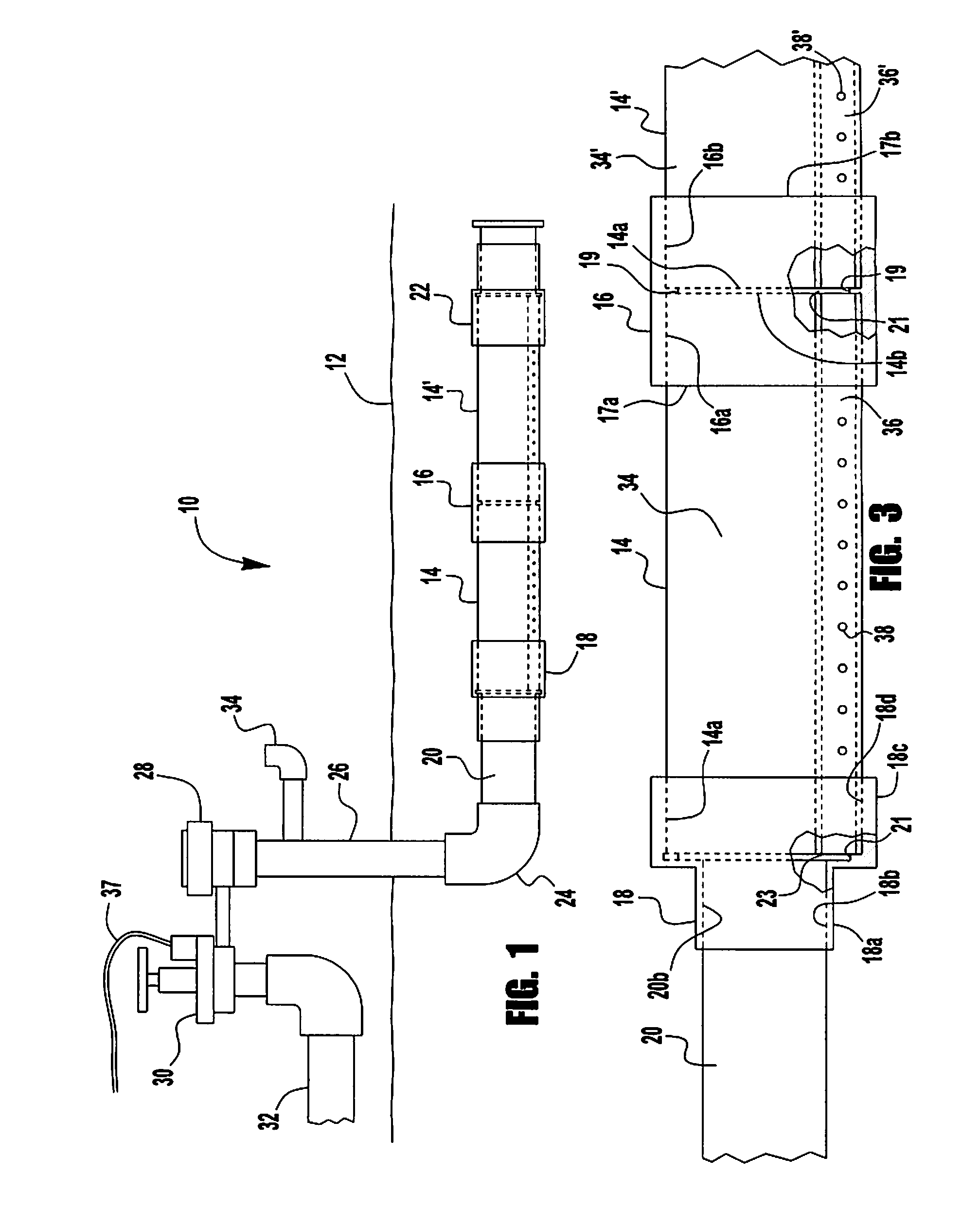
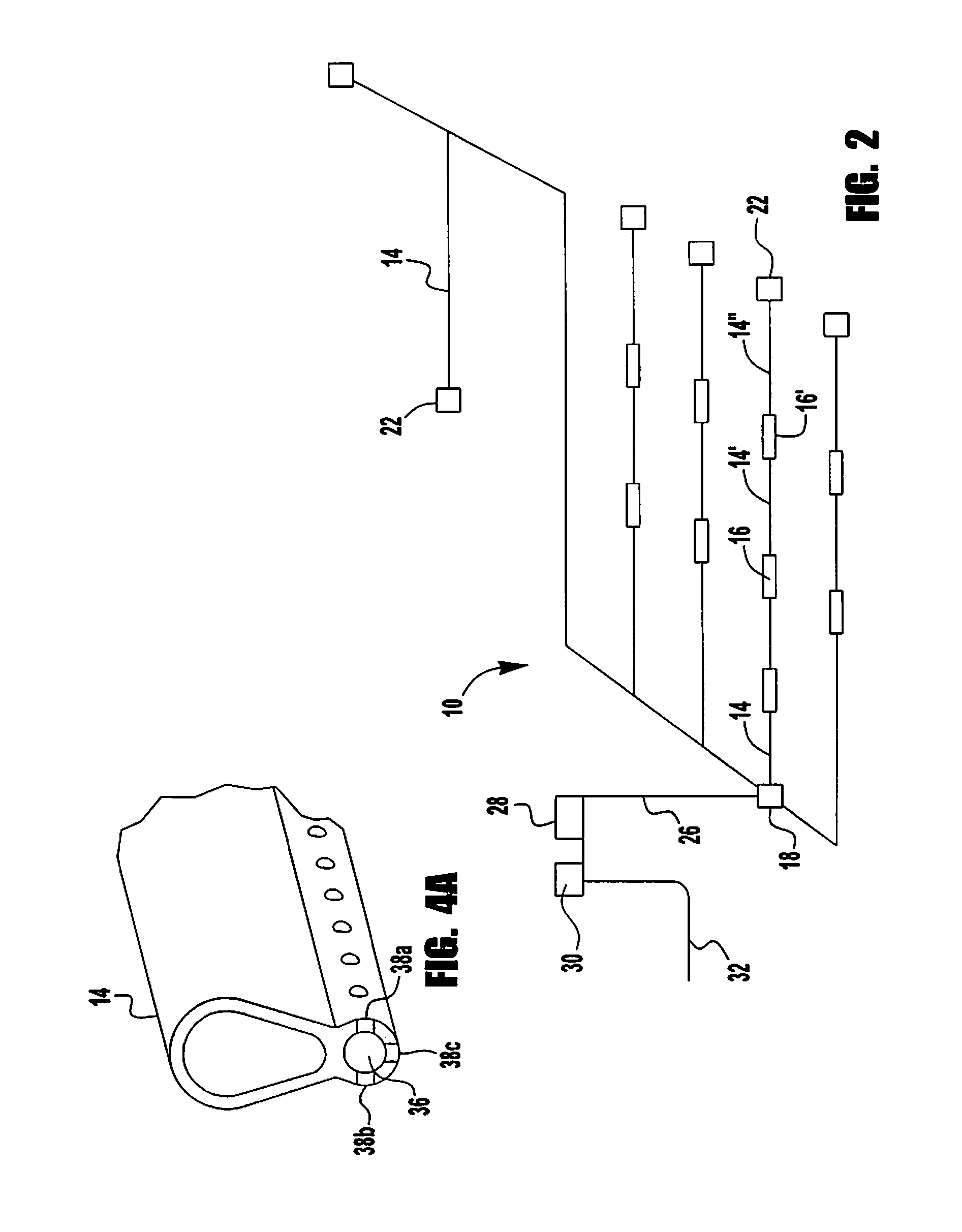
[0043]FIG. 1 illustrates the basic components of an irrigation pipe system 10 which is preferably buried below ground surface 12 to any desired depth such as for example, 5 cm to 50 cm. The depth of the irrigation pipe system 10 preferably corresponds to the depth of the roots of the agricultural growth which is being irrigated. As shown in FIG. 2, the irrigation pipe system 10 can be laid out in any desired configuration as discussed in more detail herein after.

[0044]The primary components of the irrigation pipe system 10, as shown in FIG. 1, can include an irrigation pipe section 14, an irrigation pipe section coupling 16 adapted for connecting two irrigation pipe sections 14 and 14′ together as shown in FIGS. 1 and 3, an irrigation pipe section inlet end coupling 18 adapted for connecting an irrigation pipe section 14 to a conventional inlet pipe 20, and an irrigation pipe section outlet end coupling 22 adapted for closing an end of a length of interconnected irrigation pipe sect...


PUM


Abstract

According to the present invention, an irrigation system pipe system 10 for aerating and watering a tract of land includes a first irrigation pipe section 14 having first and second isolated flow channels 34, 36, extending between the inlet and outlet ends 14a, 14b of the pipe section 14, the second flow channel 36 having a plurality of openings formed therethrough; a second irrigation pipe section 14′ having first and second Isolated flow channels 34′, 36′, extending between the inlet and outlet ends 14a′, 14b′ of the pipe section 14′, the second flow channel 36′ having a plurality of openings 38 formed therethrough; and coupling means 16 for interconnecting the first and second irrigation pipe sections 14, 14′ so that water flowing through the first flow channels 34,34′ and through the second flow channels 36, 36′ can flow between the first and second flow channels of the first and second irrigation pipe sections.

Description

CROSS-REFERENCE TO RELATED APPLICATIONS[0001]This application claims the benefit of U.S. Provisional Patent Application No. 60 / 745,308 filed on Apr. 21, 2006 which is incorporated herein by reference.[0002]This application also claims the benefit of International Application No. PCT / US2007 / 67211 filed on Apr. 23, 2007 which is incorporated in its entirety herein by reference.TECHNICAL FIELD[0003]The present invention relates generally to a irrigation system, and more particularly to an underground irrigation system which will minimize use of water due and allow for continued use for long periods of time without the need for cleaning.BACKGROUND OF THE INVENTION[0004]Underground sprinkler systems incorporating sprinkler nozzles have long been utilized to provide irrigation water to lawns, gardens and shrubbery. The primary advantage of such sprinkler systems is their lack of visibility when the system is not operating since the pipes interconnecting the sprinkler nozzles are concealed...

Claims


Application Information

Patent Timeline
IPC IPC(8): E02B13/00
CPCA01G25/06
Inventor RICHARDSON, KENNETH O.
Owner GREEN HYDROTEC
Learn More