
Race Track Lighting Fixture and Race Track lighting System

a lighting fixture and race track technology, applied in the field of track lighting, can solve the problems of not taking into account special needs and not addressing problems, and achieve the effect of reducing the number of lamps on the track, improving the lighting effect, and improving the lighting

Active Publication Date: 2009-02-26
QUALITE SPORTS LIGHTING LLC
View PDF29 Cites 5 Cited by
  • Summary
  • Abstract
  • Description
  • Claims
  • Application Information

AI Technical Summary

Benefits of technology

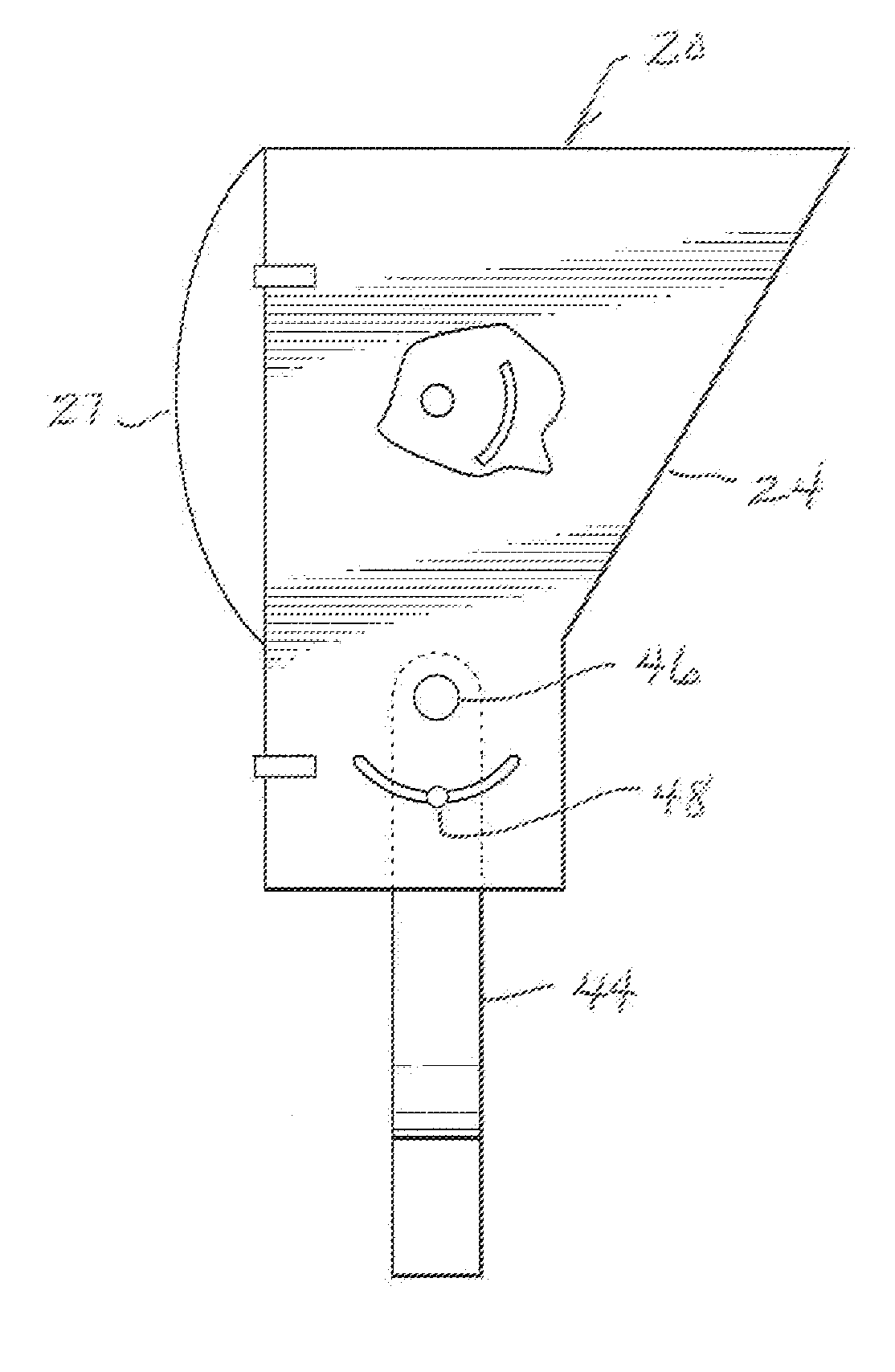
[0005]According to one aspect of the invention, there is provided a lighting fixture providing an asymmetric output profile characterized by a strong cut off in one lateral direction and divergent light in the other direction. Such a fixture is particularly suitable for race track lighting and includes a housing having a lateral axis of symmetry and a reflective inner surface. The term “lateral axis” is intended to mean that the axis of symmetry is cross-wise to the direction of transmitted light. An elongate high-intensity lamp is mounted in the housing with its are axis corresponding essentially with the axis of symmetry. The fixture further comprises an angled reflective side plate disposed in the housing to produce a laterally divergent light output from one side of the fixture.

Problems solved by technology

While these systems may provide adequate lighting of the track surface for racing purposes, they do not take into account the special needs associated with televised night racing nor do they address the problems associated with the projection of high-intensity, divergent light beams into the direction of oncoming traffic.

Method used


Image

  • Race Track Lighting Fixture and Race Track lighting System
  • Race Track Lighting Fixture and Race Track lighting System
  • Race Track Lighting Fixture and Race Track lighting System

Examples


Embodiment Construction

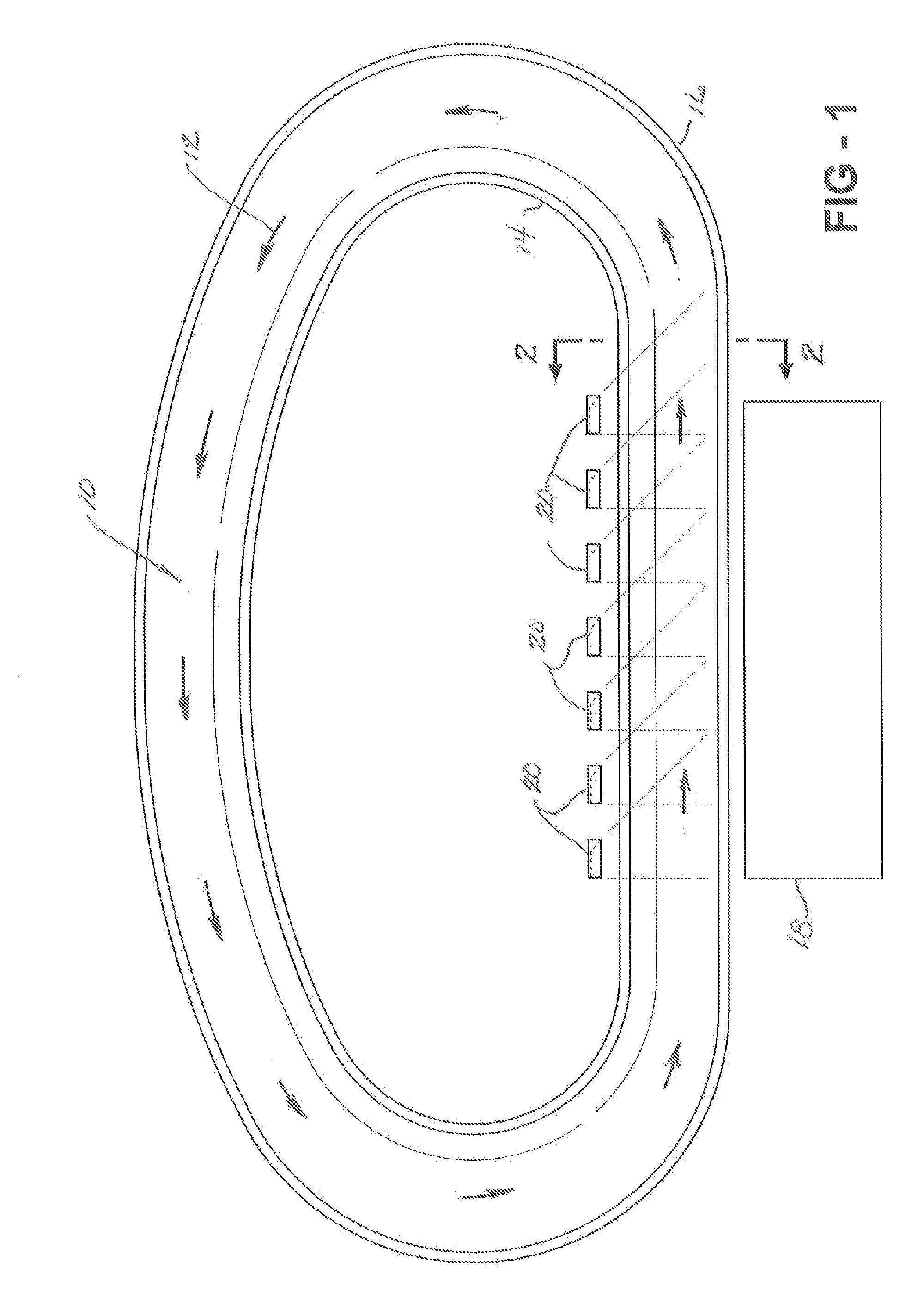
[0017]FIG. 1 shows in plan view an oval race track 10 having a clockwise direction of traffic flow defined by the arrows 12 in accordance with the standard practice in the United States for NASCAR, IRL and other classes of racing. An oval is merely exemplary as the invention can be used in connection with irregular road courses and various other shapes. The track 10 is provided with an infield side retainer wall 14 and a primary viewing side retainer wall 16. Located adjacent the track 10 is a grandstand 18 shown simply for illustrative purposes. It is understood that many tracks have grandstand or bleacher or deck seating all around as well as seating on the infield side. In this application, the term “primary viewing side” refers to the side of the track in a defined area where spectators are primarily located, usually the outside of a closed circuit track.

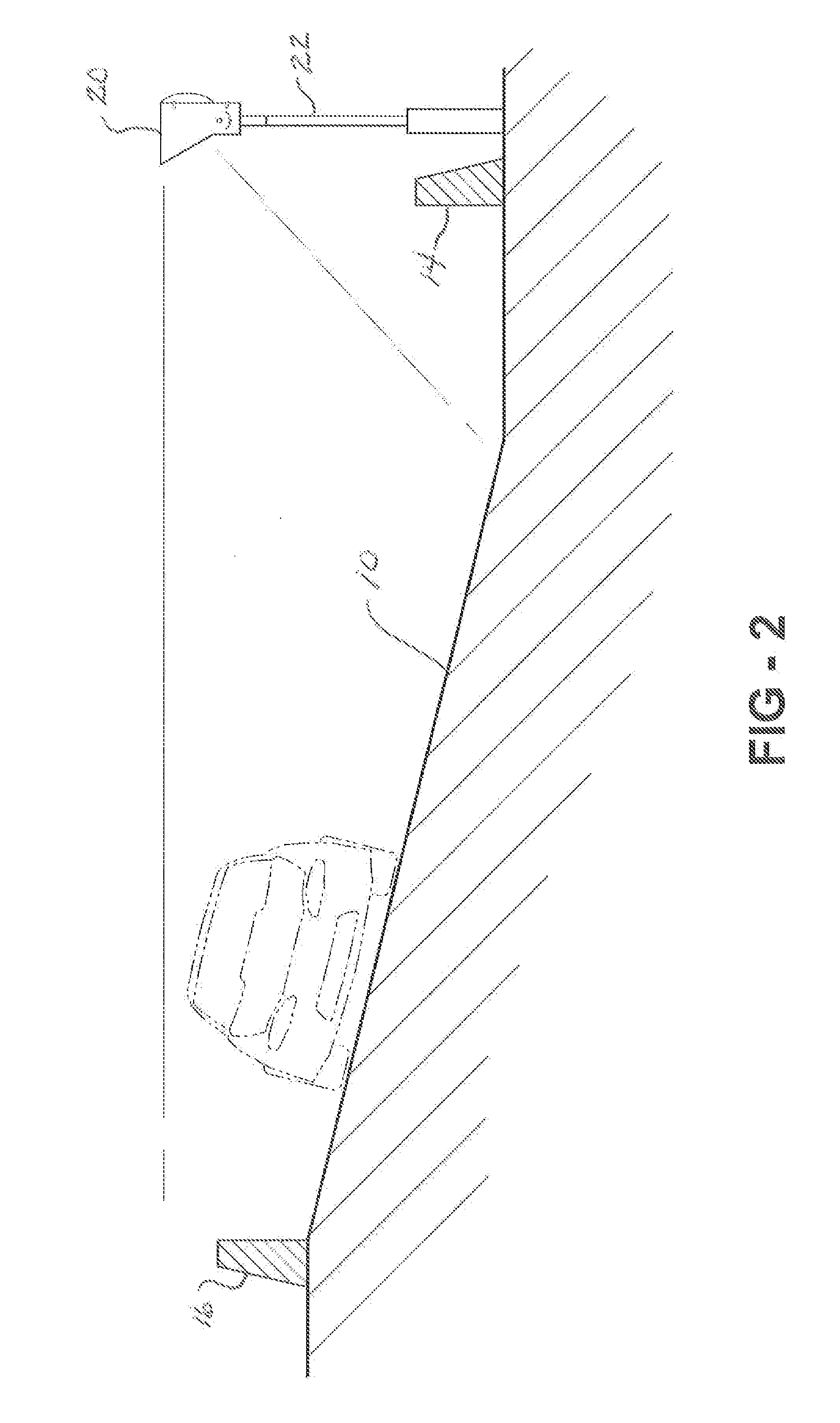
[0018]In accordance with the invention and as shown in FIGS. 1 and 2, a plurality of lighting fixtures 20 are arranged in a li...


PUM


Abstract

A race track lighting system comprising a plurality of fixtures mounted in spaced relationship to one another on the infield side of the track and projecting light outwardly and downwardly onto the track surface from relatively low poles. Each fixture is asymmetric so as to provide a strong cut-off preventing light from being projected, into the eyes of oncoming driver, but a divergent pattern in the direction of traffic flow so as to blend the light from one fixture with the light from an adjacent fixture for the purpose of promoting uniformity in the lighting intensity. The lamp is offset in the fixture and a blocker strip is placed in from of the lamp to prevent direct, uncontrolled light, from reaching the track.

Description

FIELD OF THE INVENTION[0001]This invention relates to track lighting and more particularly to a high intensity lighting fixture with an asymmetric output profile suitable for illuminating the surface of a race track.BACKGROUND OF THE INVENTION[0002]Conventional high intensity lighting fixtures comprise are discharge lamps mounted in parabolic reflectors to create a securely symmetric output profile. Hoods, shields, and other devices to modify the output profile are known.[0003]Race track lighting comprises high intensity fixtures mounted in multiples on high poles around fee perimeter of the track in much the same manner as one finds in football stadium lighting. While these systems may provide adequate lighting of the track surface for racing purposes, they do not take into account the special needs associated with televised night racing nor do they address the problems associated with the projection of high-intensity, divergent light beams into the direction of oncoming traffic.[0...

Claims


Application Information

Patent Timeline
Patent Type & Authority Applications(United States)
IPC IPC(8): F21S13/14F21V7/00
CPCF21S8/086F21W2131/105F21W2131/103F21V7/0008
Inventor HAMMEL, JEFFREY L.
Owner QUALITE SPORTS LIGHTING LLC
Learn More