
Patch

a skin patch and plaster technology, applied in the field of skin patches or plasters, can solve the problems of skin irritation, and many pharmaceutical active substances are not suitabl

Inactive Publication Date: 2009-02-19
VAN ROOYEN QUINTON +4
View PDF4 Cites 4 Cited by
  • Summary
  • Abstract
  • Description
  • Claims
  • Application Information

AI Technical Summary

Benefits of technology

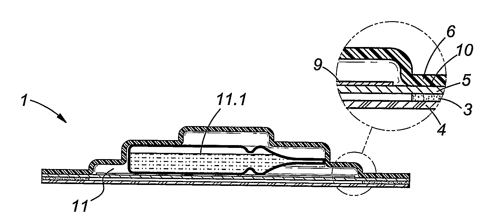
[0014]The use of a glass ampoule may permit an extensive shelf life for the patch as aggressive or sensitive components of the composition to be administered are stored in a glass container extending the shelf life of the patch. The use of glass for the ampoule provides for reliable release of the contents of the container into the cavity once the ampoule is broken by crushing between the fingers of a user.
[0026]Without wishing to be bound by theory it is believed that one of the reasons why DMF leads to erythema is that the water content of perspiration released by the skin under a patch reacts with DMF to form an irritant, possibly formic acid if allowed to remain on the skin in a quantity that is greater than the quantity which the skin is capable of absorbing. By the present invention it is sought to provide a means whereby such irritants as DMF will be released at a required dose and at a rate below the rate at which skin absorption of such substance will take place, thereby ensuring that no build-up of such substances occurs on the skin. It provides a solution to the problem in that it materially reduces, if not completely eliminates, the occurrence of erythema. The invention accordingly specifically provides for a patch suitable for use in the administration of DMF to a patient and characterised in that the proximal layer of the patch has a permeability to DMF such that DMF which is, in use, located in the cavity between the layers will be released through the proximal layer at a rate below the rate at which it is absorbed through the skin of the patient to which the patch is in use applied, thereby substantially preventing build-up of DMF in direct contact with the skin of the patient.
[0037]A polypropylene film may be located within the cavity between the disruptable container and the proximal layer. The polypropylene film may act as a shield to inhibit shards of the disrupted container from piercing the proximal layer.

Problems solved by technology

It is also known that many pharmaceutical active substances are not suitable as such for transdermal administration as they are not readily absorbed through the skin or cause irritation to the skin when applied directly to the skin.
It is however further known that some of the known penetration enhancing agents and other excipients conventionally used in the formulation of pharmaceutical preparations cause irritation when applied to the skin.
One of the difficulties with a patch such as that disclosed in the above PCT application is that the depot cavity which is formed between the proximal and distal layers is filled by a user with one or more of a carrier substance and the active irritating substance which does not ensure the correct dosage regime.
Furthermore, shelf life issues also arise as the patch is made from a porous material.
There has however not been a suitably reliable transdermal administration device that can be used for the purpose of administering DMF at the low and sub-toxic dosages that are considered necessary to apply such proposed treatment.
One of the difficulties with applying DMF by means of conventional transdermal devices, is that it causes severe skin irritation in the form of pruritic erythema.
DMF is in addition also a solvent for a large number of synthetic materials, and permeates through a number of others, both of which factors limit the choice of materials which may be used in constructing a patch suitable for use in administering DMF or DMF containing compositions to a patient-human or animal.

Method used


Image

  • Patch
  • Patch

Examples


Embodiment Construction

[0046]An example of the present invention will now be described merely to illustrate the invention and without thereby limiting the scope of the invention to the exemplary embodiment.

[0047]FIG. 1: In this Figure is shown a sectional view of an embodiment of a patch in accordance with the invention; and

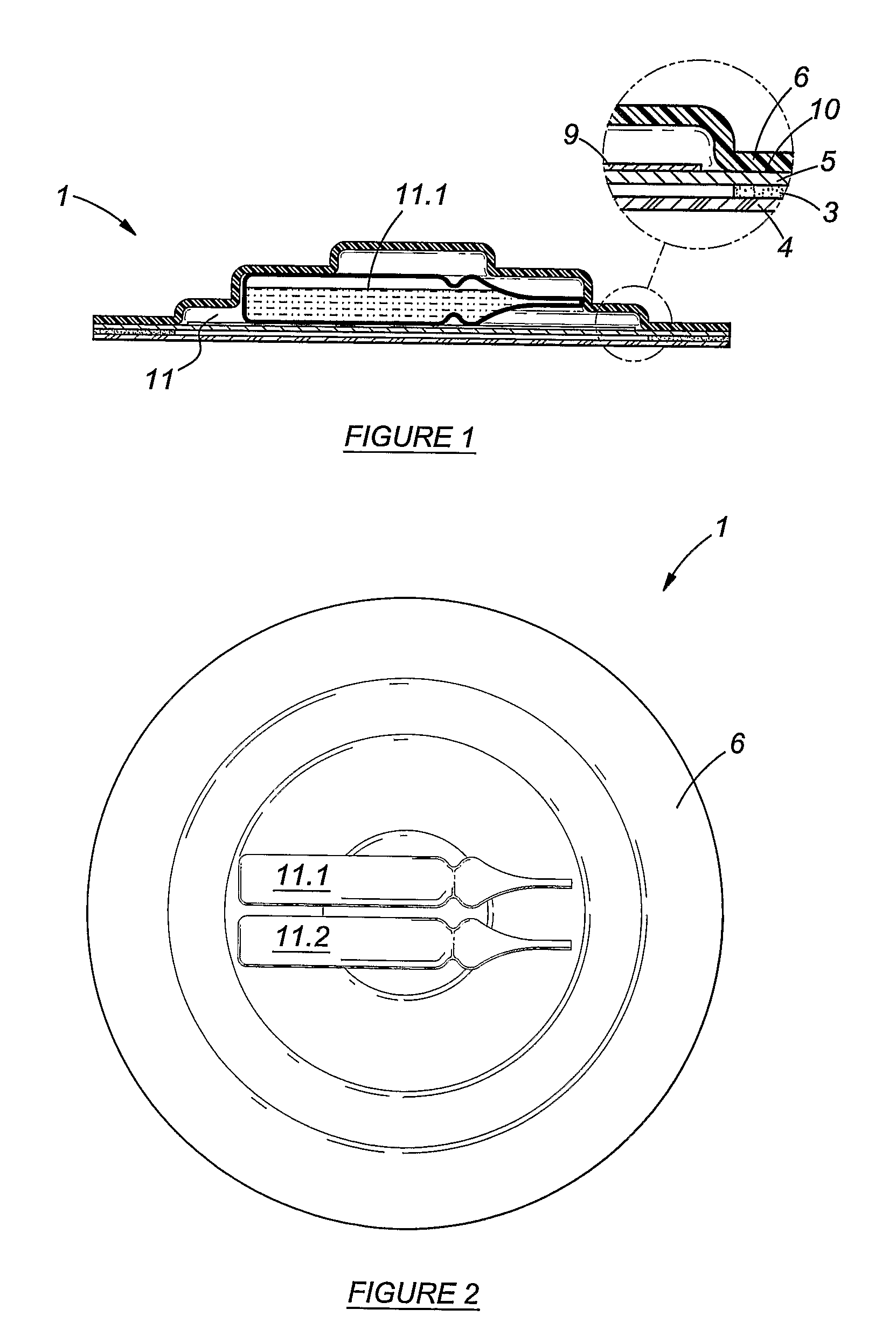
[0048]FIG. 2: In this Figure is shown a top view of another embodiment of the patch of FIG. 1, this embodiment having two containers for components of a composition or for a composition.

[0049]It is emphasised that the drawings are not to scale, and are of a schematic nature. The dimensions of some parts of the patch may be exaggerated for illustrative purposes.

[0050]Reference will now be made to the accompanying drawings in which the same reference numerals are used to indicate the same elements.

[0051]A trans-dermal patch 1 is shown to comprise a skin adhesive coated backing layer 3 and a peelable cover 4. The peelable cover 4 may be removed to expose the proximal layer 5 of the patch....


PUM

PropertyMeasurementUnit
Compositionaaaaaaaaaa
Sizeaaaaaaaaaa
Volumeaaaaaaaaaa

Abstract

The invention provides a patch device adapted for use in the transdermal administration to a patient of a composition including one or more pharmaceutically, cosmetically, pesticidally, prophylactically, and nutritionally active substance, the patch consisting of a layered construct adapted to be adhered to the skin of a patient and defining a cavity for receiving one or more disruptable containers of the composition or components of the composition to be administered between a proximal layer and a distal layer thereof, which proximal layer is adapted in use to be located in intimate contact with the skin of the patient and which distal layer is in use disposed on the outer side thereof, wherein the proximal layer is partially permeable to that composition, so that in use the integrity of the one or more containers may be disrupted thereby causing the composition to be disposed in the cavity and permeate from there through the proximal layer to be absorbed through the skin into the body of the patient. The invention further provides a method of applying an irritant to the skin of a user.

Description

FIELD OF THE INVENTION[0001]This invention relates to a skin patch or plaster suitable for use in the transdermal delivery to the human or animal body of pharmaceutical active substances or compositions containing such active substances.BACKGROUND TO THE INVENTION[0002]It is well known in the field of drug delivery that certain pharmaceutical active substances may be delivered transdermally to a patient in need thereof. It is also known that many pharmaceutical active substances are not suitable as such for transdermal administration as they are not readily absorbed through the skin or cause irritation to the skin when applied directly to the skin. It is also known that the absorption of such substances through the skin of the patient may in some cases be enhanced by the use of various excipients used in the formulation of pharmaceutical preparations and in particular by the use of substances known as penetration enhancing agents. It is however further known that some of the known p...

Claims


Application Information

Patent Timeline
IPC IPC(8): A61F13/02
CPCA61K31/16A61K9/703
Inventor VAN ROOYEN, QUINTONVAN ROOYEN, CHRISTINAJONES, JOHANNESLE ROUX, ABRAHAM JOSUAPOWELL, CORNELIUS JOHANNES
Owner VAN ROOYEN QUINTON
Learn More