
Fiber-optic heterodyne imaging vibrometer

Active Publication Date: 2009-02-19
METROLASER
View PDF13 Cites 65 Cited by
  • Summary
  • Abstract
  • Description
  • Claims
  • Application Information

AI Technical Summary

Benefits of technology

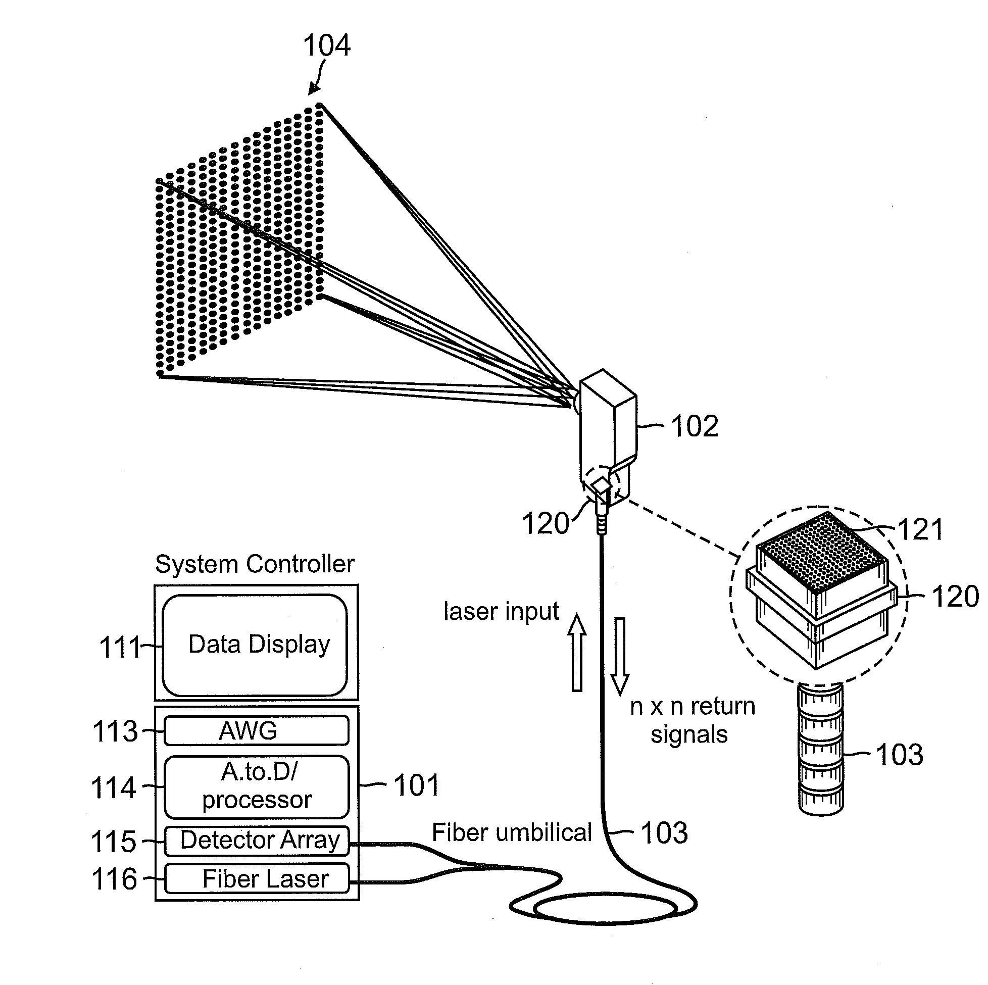
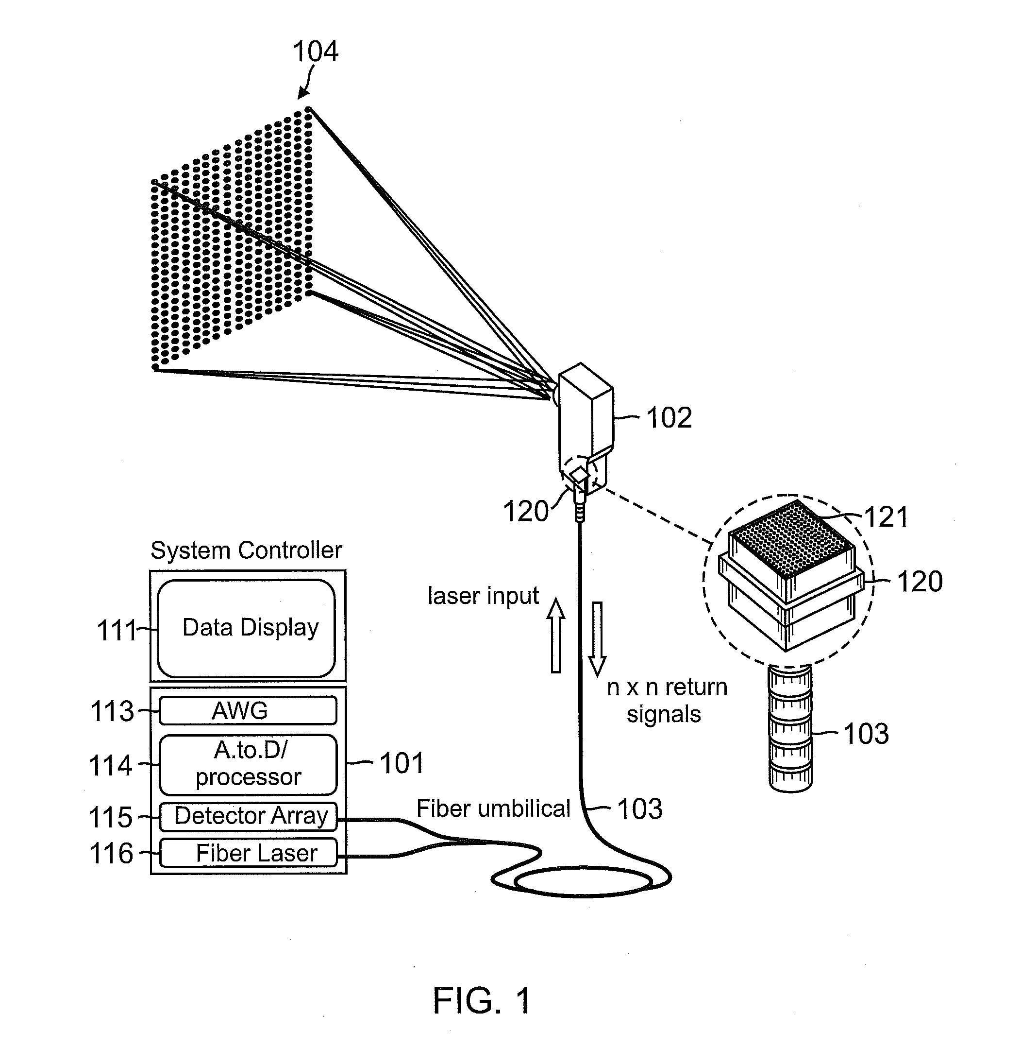
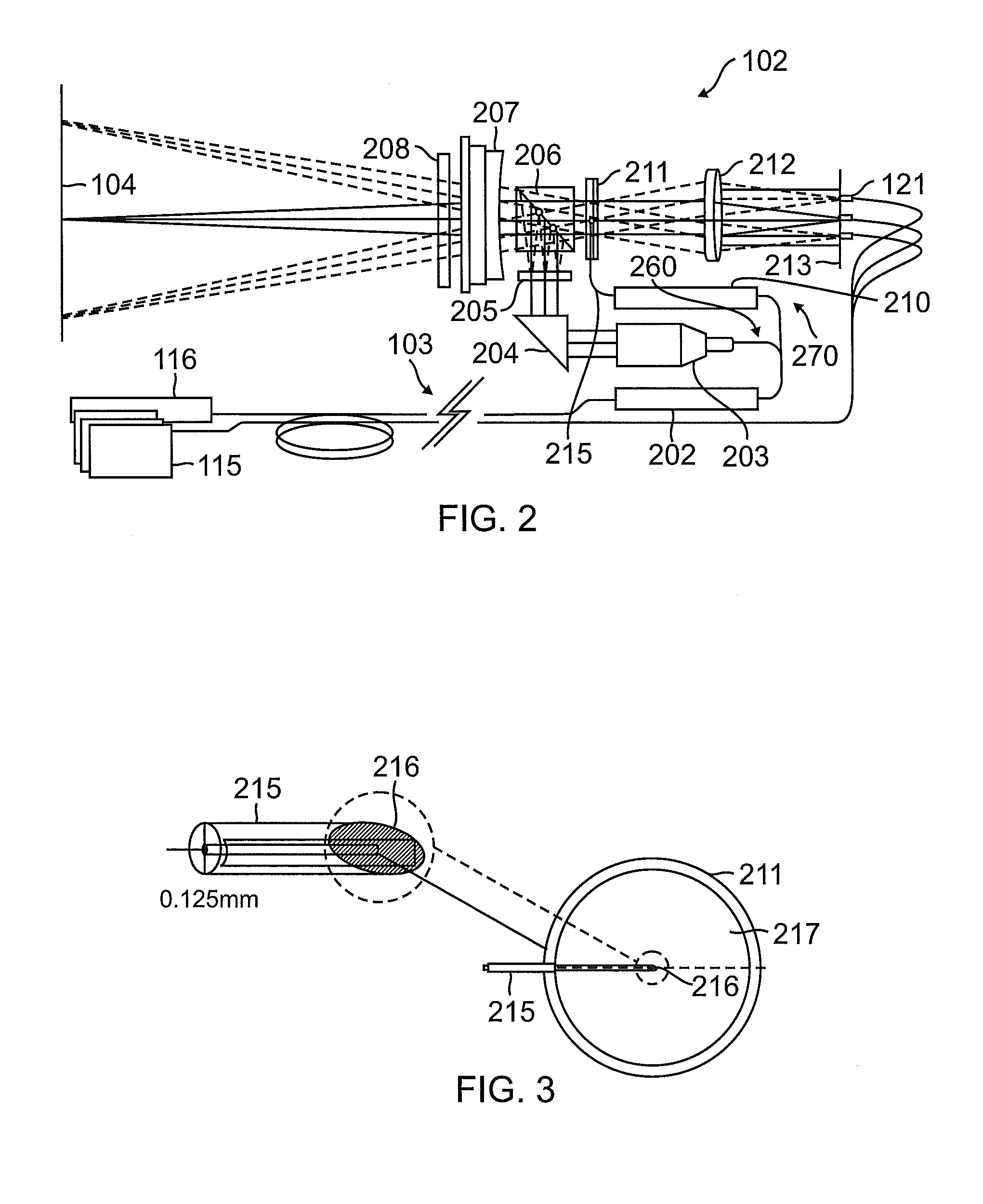
[0019]Benefits include the two-dimensional imaging of the movement, e.g., displacement, velocity and / or vibration, of a surface such as by using a compact remote inspection probe that facilitates rapid manipulation and translation over convoluted or extended surfaces. The use of such an inspection probe can facilitate structural monitoring and / or use for non-destructive inspection (NDI) applications.

Problems solved by technology

These approaches, however, assume that the measurement conditions remain invariant while multiple and, supposedly, identical, sequential measurements are performed, making this approach undesirably slow.
Most engineering environments do not satisfy these requirements.
In routine tests, natural or forced excitation can give rise to steady state and / or non-steady state vibrations which can include transients, e.g. from impact, or coupled vibrations, generated under test conditions which may be difficult, or impractical, to reproduce consistently or repeatedly.
However, such devices do not provide adequate two-dimensional information for many practical applications because of the inherent data latency associated with opto-mechanical scanning of the beam(s) over the measurement surface.
This approach is not capable of real-time vibration imaging, but is capable of synthesizing vibration images for a restrictive subset of well behaved surface vibrations.
However, as is well known, the temporal bandwidth of the proposed (commercial) camera detector arrays are insufficient to support real time vibration imaging.

Method used


Image

  • Fiber-optic heterodyne imaging vibrometer
  • Fiber-optic heterodyne imaging vibrometer
  • Fiber-optic heterodyne imaging vibrometer

Examples


Embodiment Construction

[0030]Laser Doppler vibrometry (LDV) devices using a single beam and a beam scanning system are known. Scanned single-beam techniques are suitable for measuring vibrations that are repetitive, e.g., continuously cycling at the same location. However, because the measurements are made sequentially from one location to the next, the value of this technique is limited.

[0031]Since long data acquisition cycles are required to collect two-dimensional spatially distributed data the process can incur measurement errors due to variable environmental conditions. In addition, a separate phase reference signal is essential to correctly reconstruct the two-dimensional data field from sequentially sampled data. This typically requires the physical attachment of an accelerometer cell to the surface in question or the use of a secondary fixed reference vibrometer.

[0032]A plurality of single-beam LDV systems can be used to measure multiple locations on an object to rapidly provide two-dimensional in...


PUM


Abstract

A method and system for performing two-dimensional laser Doppler vibrometry (LDV) are disclosed. A high speed fiber optic heterodyne imaging vibrometer can be used for the imaging of high speed surface deformation and / or vibration. Images provided by the high speed fiber optic heterodyne imaging vibrometer can be representative of movement, e.g., displacement or vibration, of the surface being imaged.

Description

PRIORITY CLAIM[0001]This patent application claims the benefit of the priority date of U.S. provisional patent application Ser. No. 60 / 942,606, filed on Jun. 7, 2007 and entitled Fiber-Optic Heterodyne Imaging Vibrometer (docket no. M-16953-V1 US) pursuant to 35 USC 119. The entire contents of this provisional patent application are hereby expressly incorporated by reference.GOVERNMENT LICENSE RIGHTS[0002]The U.S. Government has a paid-up license in this invention and the right in limited circumstances to require the patent owner to license others on reasonable terms as provided for by the terms of F09650-03-C-0027 awarded by the United State Air Force.TECHNICAL FIELD[0003]The present invention relates generally to optics. The present invention relates more particularly to a high speed fiber-optic heterodyne imaging vibrometer for the imaging of high speed surface deformation and / or vibration.BACKGROUND[0004]Measurement of full-field (two-dimensional), time-resolved structural vibra...

Claims


Application Information

Patent Timeline
IPC IPC(8): G01B9/02
CPCG01H9/004
Inventor KILPATRICK, JAMES MUNROMARKOV, VLADIMIR B.
Owner METROLASER
Learn More