Vehicle zone monitoring apparatus
- Summary
- Abstract
- Description
- Claims
- Application Information
AI Technical Summary
Benefits of technology
Problems solved by technology
Method used
Image

Examples
Embodiment Construction
[0043]Below, an embodiment of the present invention will be explained with reference to the figures.
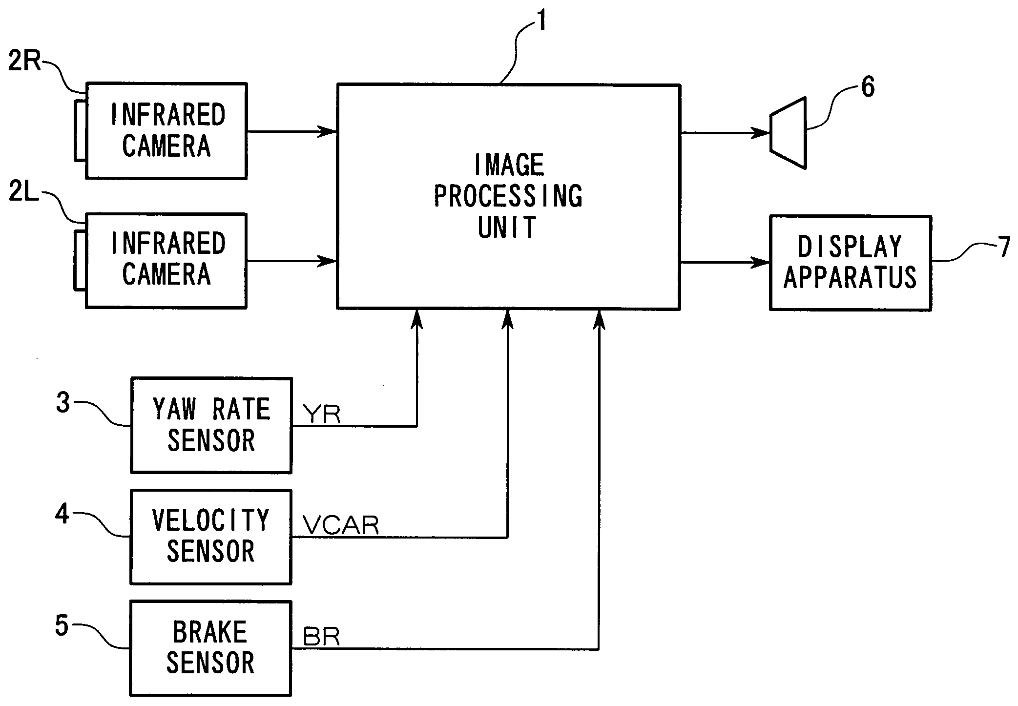
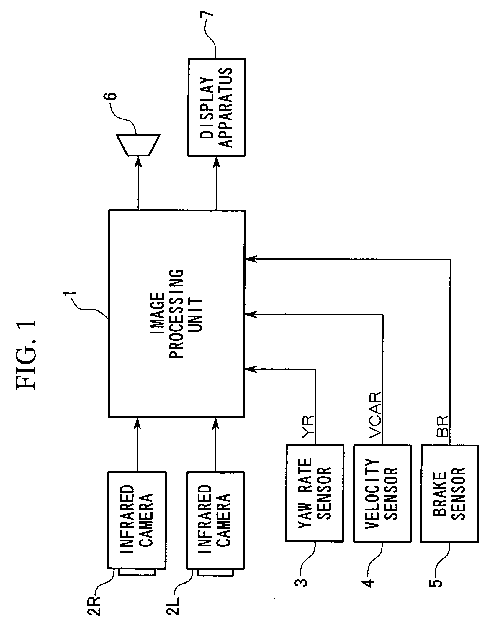
[0044]FIG. 1 is a block diagram showing the structure of the vehicle zone monitoring apparatus according to the embodiment of the present invention.
[0045]In FIG. 1, reference numeral 1 is an image processing unit that provides a CPU (Central Processing System) that controls the vehicle zone monitoring apparatus of this embodiment, and has connected thereto two infrared cameras 2R and 2L that can detect infrared light, a yaw rate sensor 3 that detects the oscillation of this vehicle physical body, a velocity sensor 4 that detects the traveling velocity (vehicle velocity) of this vehicle, and a brake sensor 5 for detecting the operation of the brake. Thereby, the image processing unit 1 detects an object that moves, such as a pedestrian or animal, in front of the vehicle from signals representing the infrared image in the vicinity of the vehicle and the travel state of the vehicle, and ...
PUM
 Abstract
Description
Claims
Application Information
 - R&D
- Intellectual Property
- Life Sciences
- Materials
- Tech Scout
- Unparalleled Data Quality
- Higher Quality Content
- 60% Fewer Hallucinations
Browse by: Latest US Patents, China's latest patents, Technical Efficacy Thesaurus, Application Domain, Technology Topic, Popular Technical Reports.
© 2025 PatSnap. All rights reserved.Legal|Privacy policy|Modern Slavery Act Transparency Statement|Sitemap|About US| Contact US: help@patsnap.com