Diesel engine and fuel injection nozzle therefor

a technology of fuel injection nozzle and diesel engine, which is applied in the direction of combustion engine, fuel injection apparatus, charge feed system, etc., can solve the problems of reducing the production of nox, not enhancing the penetration force of fuel spray, and reducing the soot production

Inactive Publication Date: 2009-02-19
MAZDA MOTOR CORP
View PDF5 Cites 8 Cited by
  • Summary
  • Abstract
  • Description
  • Claims
  • Application Information

AI Technical Summary

Benefits of technology

[0002]Some diesel engines have a so-called group hole nozzle (GHN) configured to include a plurality of injection hole groups having a plurality of injection holes for injecting fuel, such that fuel injected by each of the plurality of injection holes will form a single fuel spray cloud by each group, and thereby reduce a radius of each injection hole and atomize fuel while attaining a sufficient total flow cross sectional area of the injection holes by increasing the number of injection holes.
[0004]Using GHN technology, such as the technology described in U.S. Pat. No. 7,201,334 and enhancing fuel atomization can be useful for reducing soot emitted from a diesel engine. However, in some cases engine components such as fuel injection nozzles, combustion chambers, etc., are configured such that a fuel is ignited after the fuel collides with a wall surface of a combustion chamber to increase ignition lag of the injected fuel. In such a case, it is also important to facilitate reheating due to mixing combusted gas and surplus air by strengthening a vertical vortex in the combustion chamber, and to enhance fuel atomization to reduce soot even further, and / or to reduce nitrogen oxide (NOx) sufficiently in addition to reduction of soot.
[0005]To strengthen a vertical vortex in the combustion chamber, the penetration force of fuel spray after the fuel collides with a wall surface of a combustion chamber can be increased, which can in turn enhance swirl and penetration longitudinally along the wall surface of fuel spray and combusted gas downstream of a combustion zone, in addition to increasing a penetration force of fuel spray before the fuel reaches the wall surface.
[0008]When the mixture of fuel spray and burned gas swirling and penetrating around the wall surface rapidly reach the center of the cavity, high-temperature burned gas is cooled rapidly by mixing with low-temperature surplus air since there is low-temperature surplus air including plenty of oxygen not used for combustion around the center portion of the cavity. This can result in a decrease in NOx production and a reduction in soot by contacting soot included in burned gas with oxygen and reheating it.
[0009]Therefore, by increasing the penetration force of the fuel spray after the fuel spray collides with the wall surface, and by enhancing swirling and penetrating around the wall surface of fuel spray and combusted gas, burned gas can mix with surplus air rapidly, thereby reducing NOx and reheating soot to reduce soot in emissions.
[0012]Therefore, there is a need for providing a diesel engine that can enhance penetration force of fuel spray formed from fuel injected into a combustion chamber of engine cylinder after the fuel spay collides with a wall surface of the combustion chamber, to reduce generation of NOx and soot sufficiently.

Problems solved by technology

This can result in a decrease in NOx production and a reduction in soot by contacting soot included in burned gas with oxygen and reheating it.
So, this reference does not consider enhancement of fuel spray penetration after the fuel spray collides with the wall surface, and therefore it can not enhance penetration force of the fuel spray after the fuel spray collides with the wall surface to reduce generation of NOx and soot sufficiently.

Method used


Image

  • Diesel engine and fuel injection nozzle therefor
  • Diesel engine and fuel injection nozzle therefor
  • Diesel engine and fuel injection nozzle therefor

Examples


Embodiment Construction

[0029]Hereafter, an embodiment of the present invention will be explained based on the appended drawings.

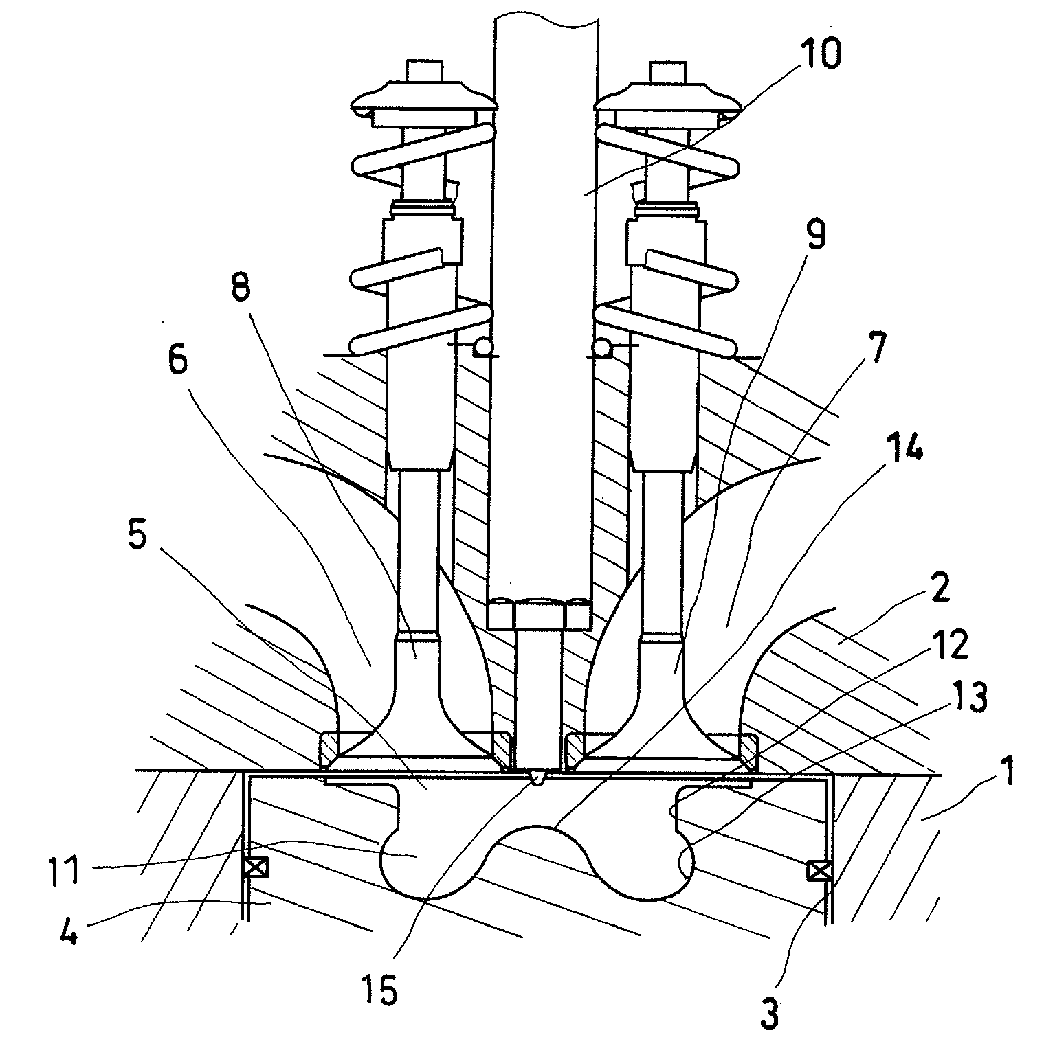
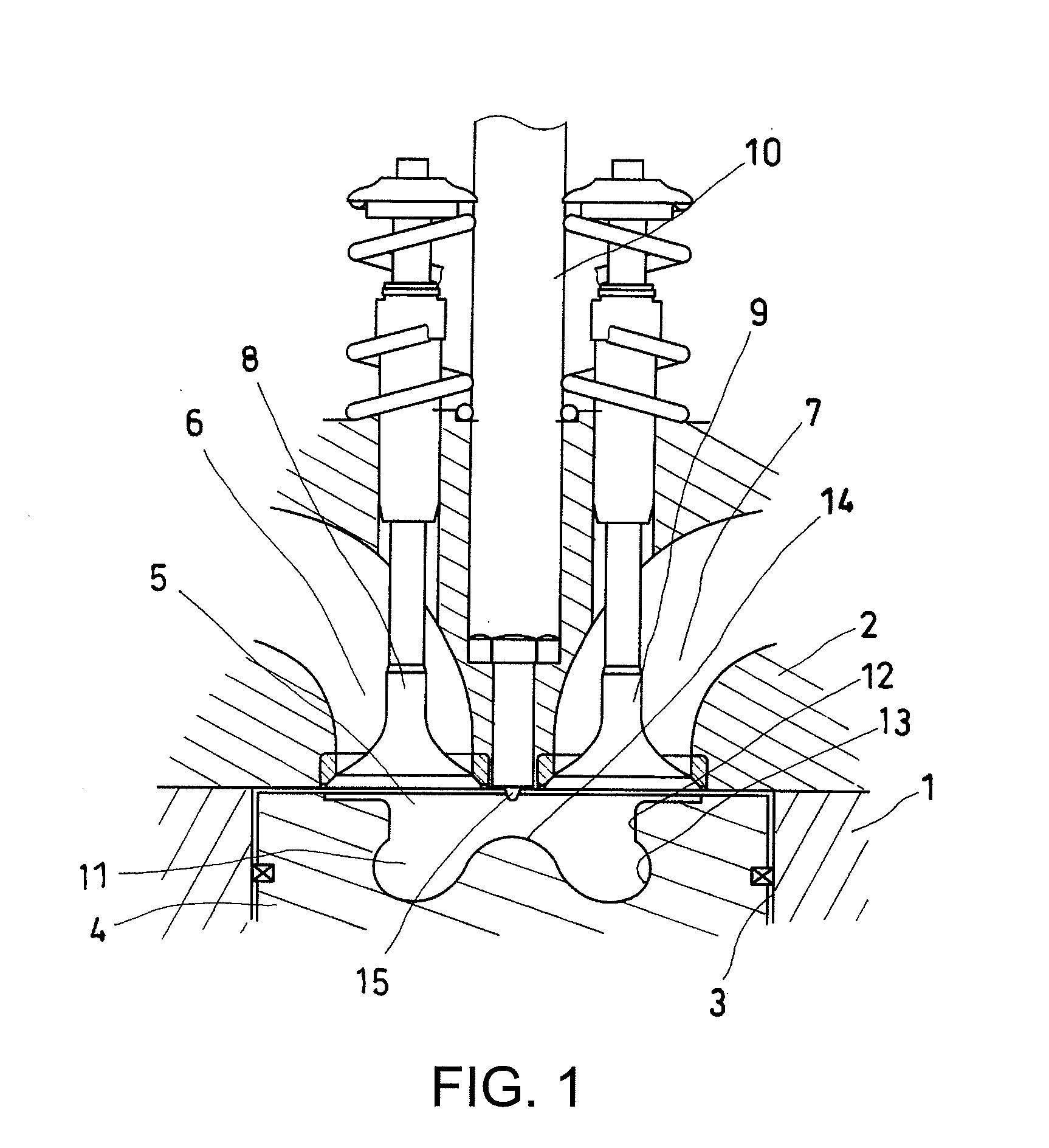
[0030]FIGS. 1-5 show an embodiment of the present invention. FIG. 1 is a cross-sectional view of a diesel engine in proximity to a combustion chamber according to this embodiment. FIG. 2 shows a wall-surface colliding point distance X of fuel sprays 2 (described later). FIGS. 3A-3C show layout parameters of fuel-injection nozzle holes. Specifically, FIG. 3A shows a distance Y between the injection holes and an angle α between the injection holes in the longitudinal cross-section of the nozzles. FIG. 3B shows a distance Z between the injection holes and an angle β between the injection holes in the lateral cross-section of the nozzles. FIG. 3C shows a lip radius “r” of the combustion chamber. FIG. 4 shows a penetration force after fuel spray clouds collide a wall surface of the combustion chamber. FIG. 5 is a graph showing a relationship between the wall-surface colliding point di...


PUM


Abstract

A fuel injection nozzle for a diesel engine. The fuel injection nozzle may include a plurality of injection hole groups, each having two injection holes respectively. A distance between the two injection holes, an angle between longitudinal axes of the two injection holes and an angle between horizontal axes of said two injection holes of each injection hole group are each set such that fuel sprays injected from said two injection holes will form a single fuel spray cloud after the fuel sprays collide with a side wall of a combustion chamber formed in a top surface of a piston of the engine, and such that the distance between collision points of the fuel sprays will be in a predetermined range in which a penetration force of said fuel spray cloud along a longitudinal direction of said combustion chamber received after collision with said wall of said combustion chamber is at or near a predetermined maximum value.

Description

TECHNICAL FIELD[0001]The present description relates to a diesel engine injecting fuel into a combustion chamber formed in a cylinder. More particular, the description pertains to a diesel engine comprising a fuel injection nozzle having a plurality of injection hole groups, each having two injection holes, respectively.BACKGROUND AND SUMMARY[0002]Some diesel engines have a so-called group hole nozzle (GHN) configured to include a plurality of injection hole groups having a plurality of injection holes for injecting fuel, such that fuel injected by each of the plurality of injection holes will form a single fuel spray cloud by each group, and thereby reduce a radius of each injection hole and atomize fuel while attaining a sufficient total flow cross sectional area of the injection holes by increasing the number of injection holes.[0003]One example of this type of diesel engine is described by U.S. Pat. No. 7,201,334. This reference describes addressing soot (black exhaust) reductio...

Claims


Application Information

Patent Timeline
IPC IPC(8): F02M51/00
CPCF02M61/1806F02M45/086
Inventor SHIMO, DAISUKEFUJIMOTO, MASAHIKOKATAOKA, MOTOSHIKIM, SANGKYUFUKUDA, DAISUKE
Owner MAZDA MOTOR CORP
Why Eureka
Try Eureka