Magnetic tape apparatus

a tape machine and tape technology, applied in the direction of instruments, data recording, record carrier guidance, etc., can solve the problems of error generation of reading out data, no running system of the magnetic tape machine, etc., and achieve the effects of less abraded, low production cost, and higher certainty

Active Publication Date: 2009-02-12
FUJIFILM CORP
View PDF9 Cites 0 Cited by
  • Summary
  • Abstract
  • Description
  • Claims
  • Application Information

AI Technical Summary

Benefits of technology

[0007]An object of the invention is to solve such drawbacks in the prior art, and provide a magnetic tape apparatus wherein the running of a magnetic tape is very stable, such as a servo writer capable of writing precise servo signals, which have a constant distance from a benchmark edge, and a magnetic tape drive wherein reading errors due to deviation from a track are not generated.
[0021]When the air entrained by the magnetic tape is excluded through the air passage disposed along the contacting face or disposed to penetrate through the inside of the fixed guide unit, the swing of the tape in the width direction thereof can be more stably decreased.
[0023]When the fixed guide unit is arranged on each of the upstream side and the downstream side of the magnetic head in the running direction of the magnetic tape, the swing of the tape in the width direction thereof can be more stably decreased in spite of the running direction of the magnetic tape.

Problems solved by technology

However, generally-used magnetic tape drives do not have any running system the precision of which is equivalent to that of servo writers from the viewpoint of costs and the durability of magnetic tapes against repeated use thereof.
Even if a servo signal is precisely written on a magnetic tape, the magnetic tape is swung in the width direction thereof when the tape runs in a drive, so that servo control cannot follow the movement of the tape.
As a result, errors of reading out data may be generated.

Method used


Image

  • Magnetic tape apparatus
  • Magnetic tape apparatus
  • Magnetic tape apparatus

Examples


examples

[0055]The invention will be described in detail by way of the following examples.

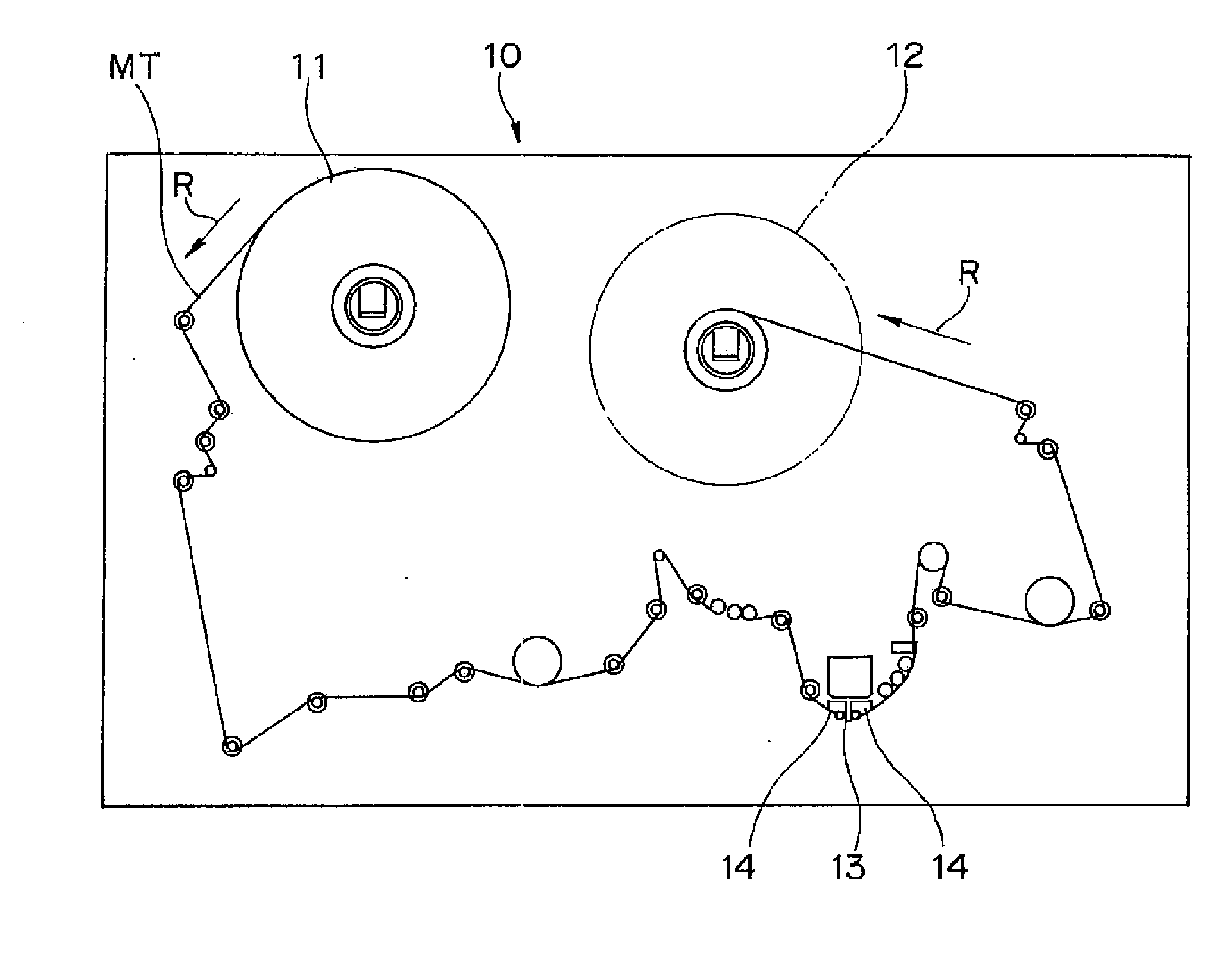
[0056]The servo writer illustrated in FIG. 1 was used to cause a magnetic tape MT to run under various conditions described in Table 1, and the swing of the magnetic tape MT in the width direction and the edge damage thereof were measured and then the conditions were evaluated. The magnetic tape MT used for the evaluation was a magnetic tape wherein a nonmagnetic undercoat layer and a magnetic layer formed were successively formed on one of two surfaces of a flexible support and a back coat layer was formed on the other surface. The servo writer illustrated in FIG. 1 was used to write a servo signal on the surface on which data signals were to be recorded (magnetic layer surface).

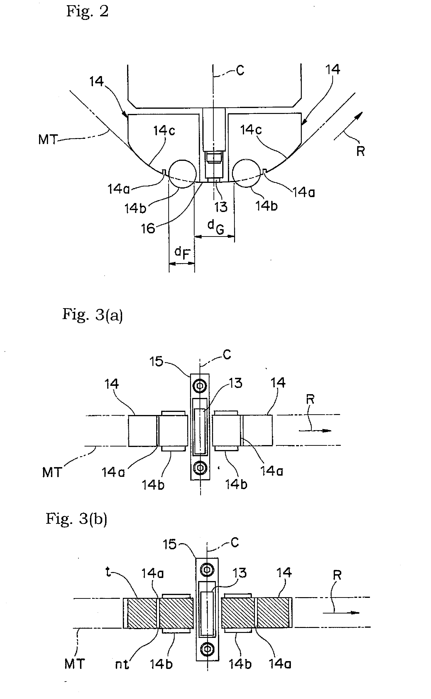
[0057]A transmission type optical sensor for detecting the position in the width direction of the upper edge of the magnetic tape MT was set up at a measurement position between the magnetic head 13 and the fixed guide unit 14 ...


PUM


Abstract

A magnetic tape apparatus includes a feeding unit for feeding a magnetic tape; a take-up unit for taking up the magnetic tape, a magnetic head disposed the downstream of the feeding unit and the upstream of the winding unit, in a traveling path of the magnetic tape from the feeding unit to the take-up unit, and having the moving magnetic tape abut to the magnetic head; a fixed guide unit disposed adjacent to the magnetic head at least in the upstream on downstream of the traveling direction of the magnetic tape traveling on the traveling path toward the magnetic head and guiding the magnetic tape to the traveling path by abutting to the magnetic tape; and a controlling unit disposed on the fixed guide unit for controlling the movement of the magnetic tape in the tape width direction. On a contact surface which abuts on the magnetic tape in the fixed guide unit, there is provided a space for excluding the air lying between the moving magnetic tape and the contact surface.

Description

TECHNICAL FIELD[0001]The present invention relates to a magnetic tape apparatus, more specifically, a magnetic tape apparatus equipped with a fixed guide unit having a regulating unit for regulating the running of a magnetic tape in the width direction thereof, and a magnetic head.BACKGROUND ART[0002]About magnetic tapes that have been used for data storage for computers in recent years, the recording density thereof has been improved to increase the recording capacity. For this purpose, in a magnetic tape having a data track in the longitudinal direction, the track width of the data track, in which data are to be recorded, becomes very narrow. For example, a recording format that the track width is 20 μm or less is suggested. When the data track width becomes narrow in such a way, it is very difficult to match the position of the data track on the magnetic tape and that of a signal reading element of a magnetic head with each other; thus, the following manner is adopted: a servo si...

Claims


Application Information

Patent Timeline
IPC IPC(8): G11B15/60
CPCG11B15/602
Inventor OTA, HIROYUKIHATA, YUKIHIROSAIKAI, JUNICHIROKUSE, SADAMU
Owner FUJIFILM CORP
Why Eureka
Try Eureka