
Optical modulator having multiple ribbon structure

Inactive Publication Date: 2009-02-12
SAMSUNG ELECTRO MECHANICS CO LTD
View PDF1 Cites 0 Cited by
  • Summary
  • Abstract
  • Description
  • Claims
  • Application Information

AI Technical Summary

Benefits of technology

[0025]The present invention provides an optical modulator having a multiple ribbon structure in which the image quality is not sensitive to environmental factors, such as time, temperature and fatigue, and / or hysteresis by driving a first driving ribbon group and a second driving ribbon group alternately.
[0026]The present invention also provides an optical modulator having a multiple ribbon structure that can correct the black level by allowing adjustment of displacement for all ribbons belonging to a first ribbon group and a second ribbon group.

Problems solved by technology

The ribbon structure interferes with the incident beam and optically modulates the signal.
However, the image quality of the open-hole type of optical modulator is sensitive to environmental factors, such as time, temperature and fatigue.

Method used


Image

  • Optical modulator having multiple ribbon structure
  • Optical modulator having multiple ribbon structure
  • Optical modulator having multiple ribbon structure

Examples


Embodiment Construction

[0041]Since there can be a variety of permutations and embodiments of the present invention, certain embodiments will be illustrated and described with reference to the accompanying drawings. This, however, is by no means to restrict the present invention to certain embodiments, and shall be construed as including all permutations, equivalents and substitutes covered by the spirit and scope of the present invention. Throughout the description of the present invention, when describing a certain technology is determined to evade the point of the present invention, the pertinent detailed description will be omitted.

[0042]Terms such as “first” and “second” can be used in describing various elements, but the above elements shall not be restricted to the above terms. The above terms are used only to distinguish one element from the other.

[0043]The terms used in the description are intended to describe certain embodiments only, and shall by no means restrict the present invention. Unless c...


PUM


Abstract

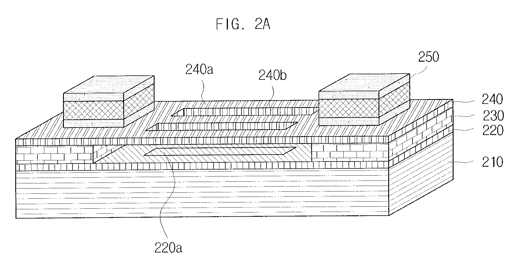
An optical modulator using a plurality of ribbons for rendering a pixel of an image is disclosed. An embodiment of the present invention provides an optical modulator having a multiple ribbon structure that can include a substrate and a first driving ribbon group and a second driving ribbon group, each of which includes at least one ribbon spaced from the substrate and driven upward or downward in accordance with a supplied voltage. A relative displacement between the first driving ribbon group and the second driving ribbon group can modulate an incident beam. By alternately driving the first driving ribbon group and the second driving ribbon group, the image quality of the optical modulator in accordance with an embodiment of the present invention can be robust against environmental factors, such as time, time, temperature and fatigue, and hysteresis.

Description

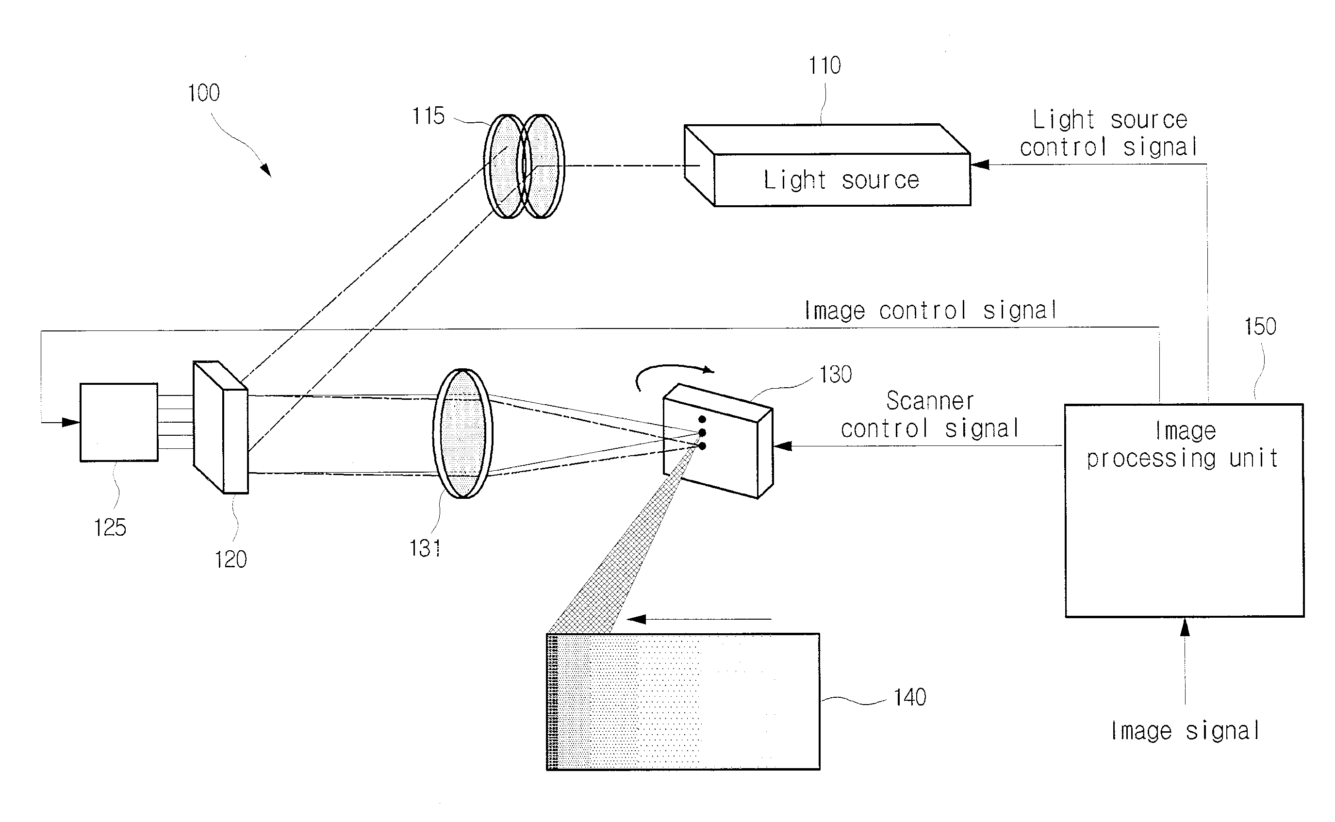
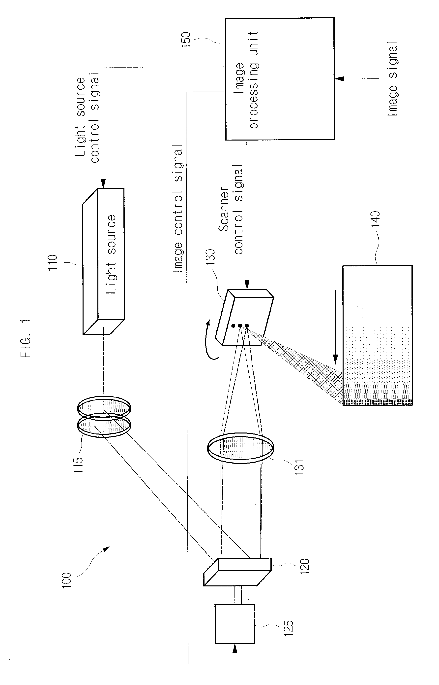
CROSS-REFERENCE TO RELATED APPLICATION[0001]This application claims the benefit of Korean Patent Application No. 10-2007-0078586, filed with the Korean Intellectual Property Office on Aug. 6, 2007, the disclosure of which is incorporated herein by reference in its entirety.BACKGROUND OF THE INVENTION[0002]1. Field of the Invention[0003]The present invention is directed to an optical modulator used in a display device, more specifically to an optical modulator using a plurality of ribbons to render a pixel of an image.[0004]2. Description of the Related Art[0005]With the recent development of projection television sets, optical modulators and scanners are used as means for scanning beams on a screen. A scanning display device using such optical modulator and scanner is illustrated in FIG. 1.[0006]A scanning display device 100 includes a light source 110, an optical modulator 120, a driving circuit 125, a scanner 130, and an image processing unit 150.[0007]An illumination optical syst...

Claims


Application Information

Patent Timeline
IPC IPC(8): G02F1/01
CPCH04N9/3129G02B26/0808G02B26/08G02B26/10
Inventor AN, SEUNG-DO
Owner SAMSUNG ELECTRO MECHANICS CO LTD
Learn More