
Directional backlight, a multiple view display and a multi-direction display

a multi-view display and backlight technology, applied in the field of multi-view directional display, can solve the problems of low average brightness of the display and difficult to achiev

Active Publication Date: 2009-02-12
SHARP KK
View PDF15 Cites 219 Cited by
  • Summary
  • Abstract
  • Description
  • Claims
  • Application Information

AI Technical Summary

Benefits of technology

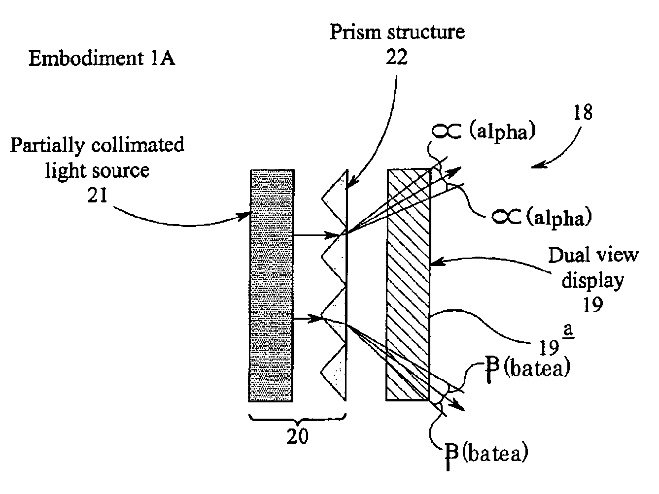
[0036]A second aspect of the invention provides a directional backlight comprising a light source and an optical arrangement for directing light from the light source at least mainly in a first range of directions and a second range of directions different from the first range of directions; wherein the optical arrangement comprises an array of substantially non-light-transmissive blocking elements and an array of imaging elements; and wherein each imaging element is substantially aligned with a respective one of the blocking elements thereby reducing or substantially preventing light from being directed between the first and second ranges.
[0058]The display may comprise a controller for repeatedly switching the backlight between the first and second modes and for controlling the device to display a first image or sequence of images when the backlight is in the first mode and a second image or sequence of images when the backlight is in the second mode. As noted above, this enables the display to operate as a time-multiplex directional display.

Problems solved by technology

This backlight has the disadvantage that light would not go to the left user and the right user simultaneously so that the average brightness of the display would be low.
Furthermore, in order to display moving images the LCD panel is required to operate at approximately 120 Hz (twice the normal picture refresh rate), and this is difficult to achieve.

Method used


Image

  • Directional backlight, a multiple view display and a multi-direction display
  • Directional backlight, a multiple view display and a multi-direction display
  • Directional backlight, a multiple view display and a multi-direction display

Examples


first embodiment

[0118]FIG. 6a is a schematic plan view of a multiple-view display 18 according to the present invention. The display 18 comprises a directional display device 19 that is able to display first and second images such that the first image is primarily visible in a first viewing window that covers a first range of directions relative to the device and for displaying a second image that is visible in a viewing window defined by a second range of directions, different from the first range, relative to the device. The first and second images displayed on the directional display device 19 may be still images, or they may be moving images (that is, the first image and second image each consist of a sequence of images). The first and second images may be displayed simultaneously and be spatially multiplexed with each other. The directional display device 19 may be a conventional multiple view directional display that comprises a spatial light modulator for displaying the first and second imag...

second embodiment

[0165]FIG. 9 is a schematic plan view of a multiple view display 18 according to the present invention. The display 18 again comprises a directional display device 19, in this embodiment a dual view display, that can display a first image so as to be mainly visible from a first range of directions relative to the device and to display a second image so as to be mainly visible from a second range of directions (different from the first range) relative to the device. The directional display device 19 is illuminated by a directional backlight 20 that directs light through the directional display device 19 at least mainly in the first and second ranges.

[0166]As in the embodiment of FIG. 6a, the directional display device 19 may be any conventional directional display, and will not be described further.

[0167]The directional backlight 20 of this embodiment comprises a light source 35 that emits light generally uniformly over its entire area. An optical arrangement for directing light from...


PUM


Abstract

A directional backlight, a multiple view display and a multi-direction display A multiple view display (18) comprises a directional display device (19) for displaying a first image or sequence of images so as to be mainly visible from a first range of directions relative to the device and for simultaneously displaying a second image or sequence of images so as to be mainly visible from a second range of directions relative to the device different from the first range. The display (18) further comprises a directional backlight (20) for directing light through the display device (19) at least mainly in the first and second ranges. Since the directional backlight (20) directs light through the display device (19) at least mainly in the first and second ranges, the display provides users located in the first and second ranges with images of greater intensity than a conventional display. The backlight may be arranged to direct substantially no light in at least part of a third range of directions that lies between the first range of directions and the second range of directions. This provides a ‘black window’ between the first and second ranges in which the intensity of the display is lower than in other ranges. The intensity of the display in the black window is possibly zero, or close to zero, so that an observer located in this window will not perceive an image.

Description

FIELD OF THE INVENTION[0001]The present invention relates to a multiple-view directional display, which displays two or more images such that each image is visible from a different direction. Thus, two observers who view the display from different directions will see different images to one another. Such a display may be used in, for example, an autostereoscopic 3-D display device or a dual view display device. The invention also relates to a multi-direction display for displaying a single image at a time so as to be visible throughout a range of directions including first and second ranges for first and second viewers. The invention also relates to a directional backlight.BACKGROUND OF THE INVENTION[0002]One application of a multiple-view directional display is as a ‘dual-view display’, which can simultaneously display two or more different images, with each image being visible only in a specific direction—so an observer viewing the display device from one direction will see one im...

Claims


Application Information

Patent Timeline
IPC IPC(8): G02F1/13357F21V8/00G02B27/22G02F1/133G02F1/1335H04N13/00
CPCB60K2350/901B60K2350/903G02B6/0011H04N13/0411G02F1/1335G02F1/1336G02F2001/133607G02F1/1323H04N13/312G02F1/133607B60K35/656B60K35/654
Inventor MATHER, JONATHANBARRATT, NEILKEAN, DIANA U.WALTON, EMMA J.BOURHILL, GRANT
Owner SHARP KK
Learn More