
Ink Circulation System For Inkjet Printing

a technology of inkjet printing and circulation system, which is applied in the field of droplet deposition apparatus, can solve the problems of operation failure of the printhead, operation failure, weeping of the nozzle,

Inactive Publication Date: 2009-02-12
AGFA NV
View PDF10 Cites 110 Cited by
  • Summary
  • Abstract
  • Description
  • Claims
  • Application Information

AI Technical Summary

Problems solved by technology

It is known that the presence of air bubbles in the ink chamber of a piezoelectric printhead often causes operational failure of the printhead.
At the frequencies at which piezoelectric transducers in piezoelectric printhead are operated, i.e. in the khz to Mhz range, not only air bubbles but also dissolved air in the ink can cause operation failure as described above.
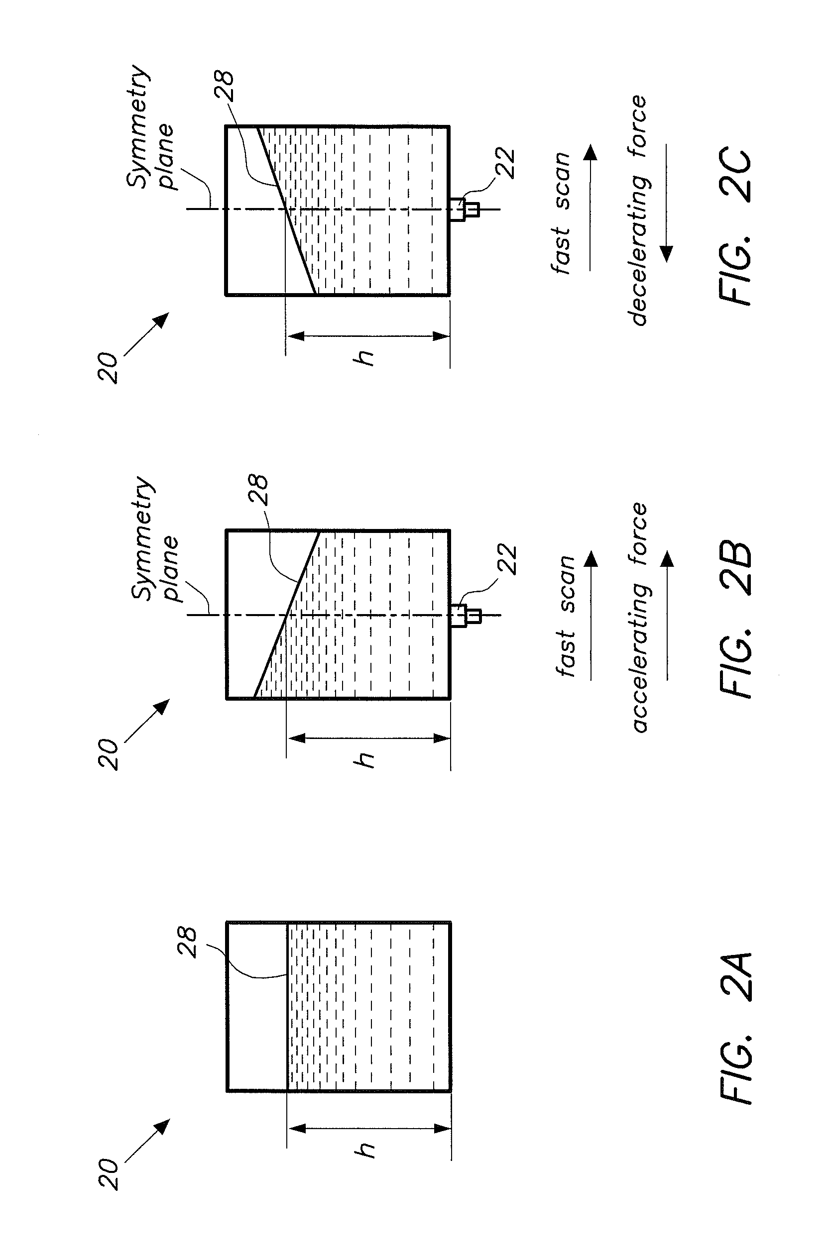
During acceleration and deceleration of the printhead, pressure waves are created in the tubes that may significantly disturb the pressure balance at the meniscus and may lead to weeping of the nozzle in the case of a decrease in negative pressure, or breaking of the meniscus in the case of an increase in negative pressure and taking air into the ink channel.
For accelerations and decelerations of the carriage above 1 G the response time of these devices is insufficient.
Although inkjet ink properties can be well controlled at manufacture and maintained at a reasonable level during transport and storage, some ink properties may degrade when the ink is used in an ink system or maintained in the printhead.
For instance, inkjet inks containing VOC's (volatile organic compounds) often suffer from evaporation of some VOC's at the ink meniscus in the nozzle.
The viscosity of the ink will change locally in the nozzle, having a negative effect on its jetting properties and potentially leading to a nozzle fall out.
Next to these problems, it has been found that if the retention time of ink in an ink supply system is too long, e.g. during production breaks or overnight, effects like settling of dispersions, auto-curing, etc. may occur.
Often these amounts of purged ink are not reusable within the printer setup.
The solutions proposed in the prior art only partially solve some of the problems described above.

Method used


Image

  • Ink Circulation System For Inkjet Printing
  • Ink Circulation System For Inkjet Printing
  • Ink Circulation System For Inkjet Printing

Examples


first embodiment

Printing Mode

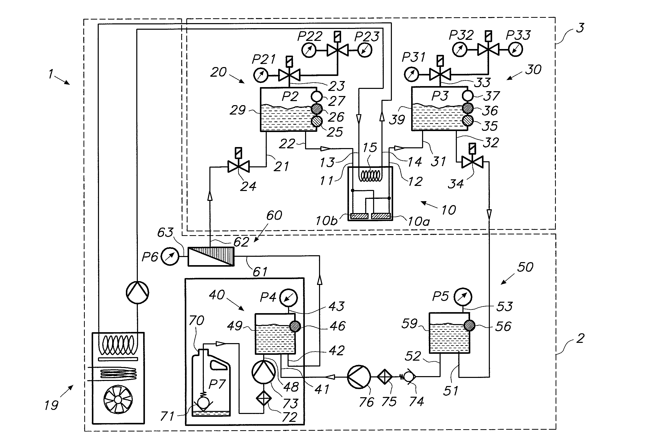
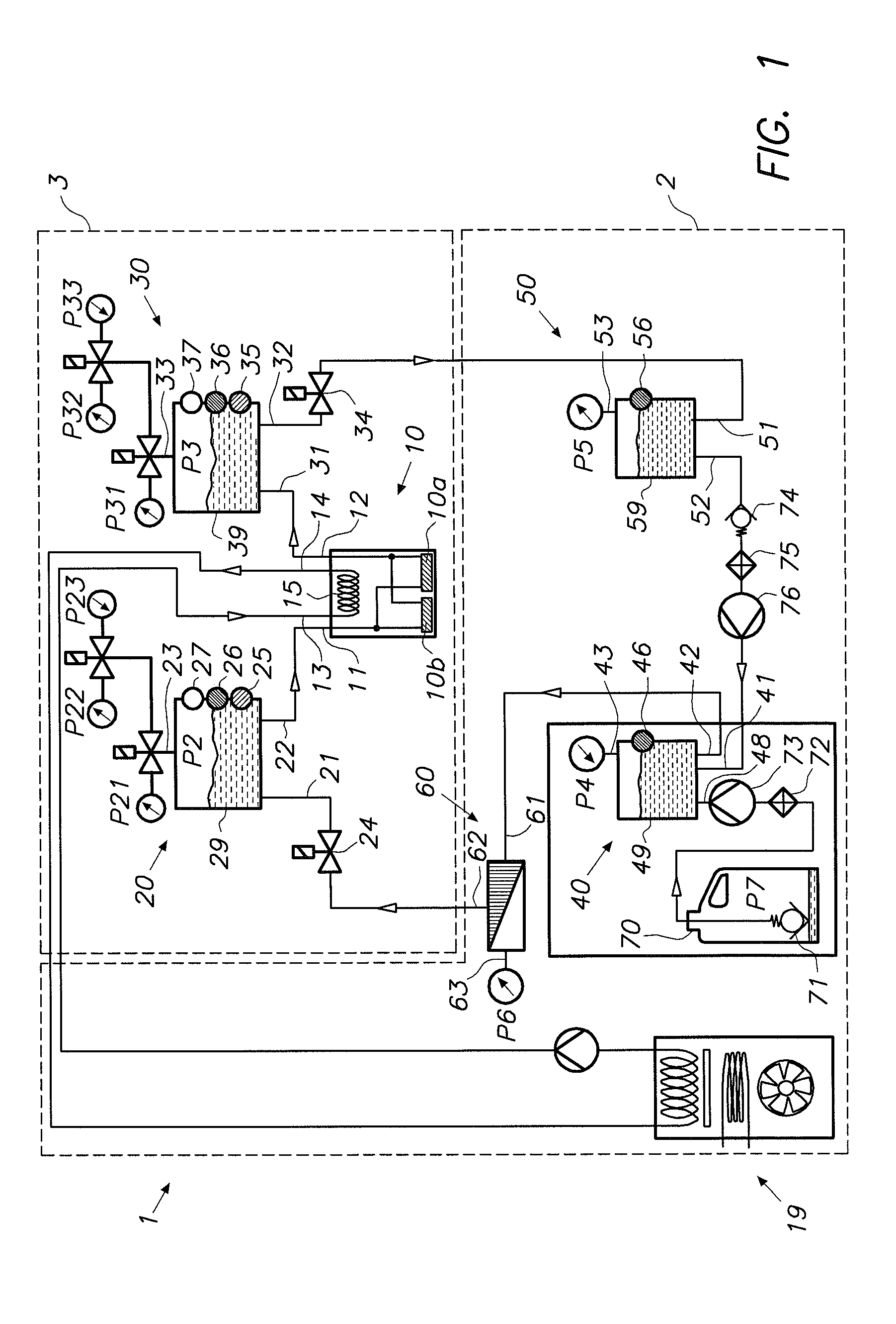
[0038]The operation of the embodiment according to FIG. 1 in normal printing mode is now being described. An ink flow through the printhead 10 is realized by establishing a pressure difference between the pressure P2 in the supply subtank 20 and the pressure P3 in the return subtank 30. These pressures are applied via pressure connection 23 on the supply subtank 20 respectively pressure connection 33 on the return subtank 30. In order to create a positive flow from the supply subtank 20 through the printhead 10 and into the return subtank 30, the pressure in the supply subtank 20 is controlled at a slightly higher value than the pressure in the return subtank 30. The ink flow rate through the printhead is controllable via pressure difference P3−P2 but depends also on the hydraulic resistance of the fluid conducts to and from the printhead as well as the flow rate of ink through these conducts, and the hydraulic resistance internally in the printhead. In practice a press...

first embodiments

Non-Printing Modes

[0047]The pressure P2 in the supply subtank 20 can be selected from at least three preset values P21, P22 and P23 that correspond to different operating conditions of the printhead 10. These preset pressure values for the supply subtank 20 cooperate with a parallel set of preset values P31, P32, P33 for the pressure P3 in the return subtank 30. A first operating condition of the printhead corresponds with a normal printing condition that has been described previously. For this purpose a set of valves (see FIG. 1) could be operated to link preset values P21 and P31 to their respective subtank.

[0048]A second operating condition of the printhead may be a purging operation, wherein the pressures applied to the nozzles is such that ink is flows out of the nozzles without actuating the nozzles. For a purging operation, equal positive pressures are applied to the supply subtank 20 and the return subtank 30. In this case there is no through-flow in the printhead 10 and all...


PUM


Abstract

An ink circulation system for use in an inkjet printing apparatus includes an inkjet printhead, a supply subtank for containing a supply of ink for the inkjet printhead and a return subtank for containing a surplus of ink not used by the inkjet printhead. The supply subtank is coupled with the return subtank and with the inkjet printhead via a first fluid path. A second fluid path couples the return subtank with the supply subtank for circulating the ink from the return subtank back to the supply subtank. This way a closed ink circulation path is realized. The ink flow from the supply subtank to the inkjet printhead and to the return subtank is controlled by means of a pressure difference between the ink in the supply subtank and the ink in the return subtank. A back pressure at the nozzle of the inkjet printhead is established via active pressure control means.

Description

FIELD OF THE INVENTION[0001]The present invention relates to droplet deposition apparatus and especially to inkjet printing apparatus. More specifically the invention is related to ink delivery systems for inkjet printers.BACKGROUND OF THE INVENTION[0002]Printers are used to print output from computers or similar type of devices that generate information, onto a recording medium such as paper. Commonly available types of printers include impact printers, laser printers and inkjet printers. The term “inkjet” covers a variety of physical processes and hardware but basically these printers transfer ink from an ink supply to the recording medium in a pattern of fine ink drops. Inkjet printheads produce drops either continuously or on demand. “Continuously” means that a continuous stream of ink drops is created, e.g. by pressurizing the ink supply. “On demand” differs from “continuous” in that ink drops are only ejected from a printhead by manipulation of a physical process to momentaril...

Claims


Application Information

Patent Timeline
Patent Type & Authority Applications(United States)
IPC IPC(8): B41J2/18
CPCB41J2/1707B41J2/18B41J2/17556
Inventor WOUTERS, PAULVERHOEST, BARTVAN DE WYNCKEL, WERNERJANSSENS, ROBERTKEMPENEERS, ERWIN
Owner AGFA NV
Learn More