
Panel light source for back-lit signs

a back-lit sign and panel light source technology, applied in lighting and heating equipment, instruments, lighting support devices, etc., can solve the problems of increasing the volume and weight of the edge lit display apparatus and the edge lit display system, and requiring considerable manufacturing, installation and maintenance costs, etc., to achieve low maintenance costs, easy installation and maintenance, and high performance

Inactive Publication Date: 2008-11-20
JUNG HAE RYONG JUNG
View PDF12 Cites 63 Cited by
  • Summary
  • Abstract
  • Description
  • Claims
  • Application Information

AI Technical Summary

Benefits of technology

[0010]Accordingly, the present invention has been made in view of the above-mentioned problems occurring in the prior art, and it is a primary object of the present invention to provide an illuminated signboard using a plane light source, which is manufactured according to the principle of edge light using LEDs, easily installed and maintained, requires low maintenance expenses, has high performance and replaces a conventional backlight signboard such as a dark light or a heavy light box manufactured using glow lamps or tube type light sources such as fluorescent lamps.
[0011]To accomplish the above object of the present invention, according to the present invention, there is provided an illuminated signboard using a plane light source in which an opaque plate having a high surface reflectivity is inserted between two flat light guide plates and the light guide plates and the opaque plate are joined to each other by means of a plurality of screws to form a single plate type secondary light source. U-shaped frames are combined with four sides of the plate type secondary light source such that the plate type secondary light source is surrounded by a frame housing. Transparent plates including graphics or natural color pictures are attached to the exposed outer side of the plate type secondary light source. PCBs and LEDs mounted on the surface of the PCBs are mounted in the frame housing such that light emitted from the LEDs is inputted to inclined edges of the light guide plates and transmitted in the light guide plates according to repeated total reflection thereof. The light transmitted in the light guide plates according to the repeated total reflection thereof is dispersed on painted faces and engraved rough faces formed on the inner sides of the light guide plates, which face the opaque plate interposed between the light guide plates. Then, the dispersed light is radiated in various directions and some of the dispersed light transmits the light guide plates and the transparent plates including the graphics and is seen by people. Accordingly, the illuminated signboard using a plane light source is thin and light, has brightness higher than a conventional light box, beautiful more than the conventional light box, is easily manufactured and maintained, and has additional functions such as color mixing and dynamic variation in illumination.
[0012]The illuminated signboard using a plane light source according to the present invention can replace various signboards including small indoor hanging signboards, conventional light boxes and even outdoor large illuminated signboards with the development of production technology of LEDs whose brightness increases and production cost decreases day by day. Furthermore, the illuminated signboard according to the present invention can reduce power consumption and remarkably decrease the manufacturing cost, installation cost and maintenance expenses.

Problems solved by technology

Furthermore, the plurality of light sources or light source groups have different colors such that lights with various wavelengths interfere in the light guide plates to achieve beautiful visual effect.
This increases the volumes and weights of the edge lit display apparatus and the edge lit display system and requires considerable costs for manufacturing, installing and maintaining the edge lit display apparatus and the edge lit display system.

Method used


Image

  • Panel light source for back-lit signs
  • Panel light source for back-lit signs
  • Panel light source for back-lit signs

Examples


Embodiment Construction

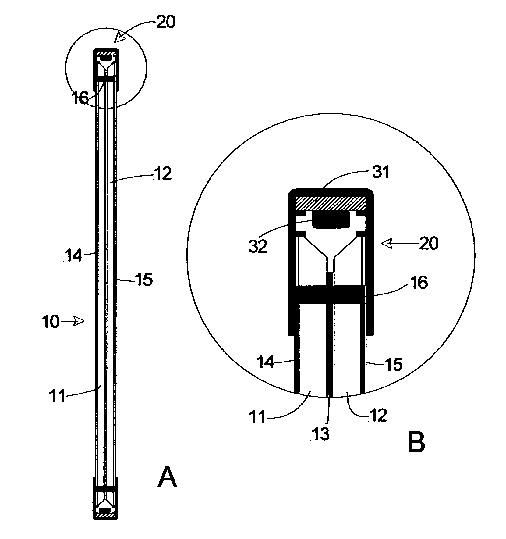
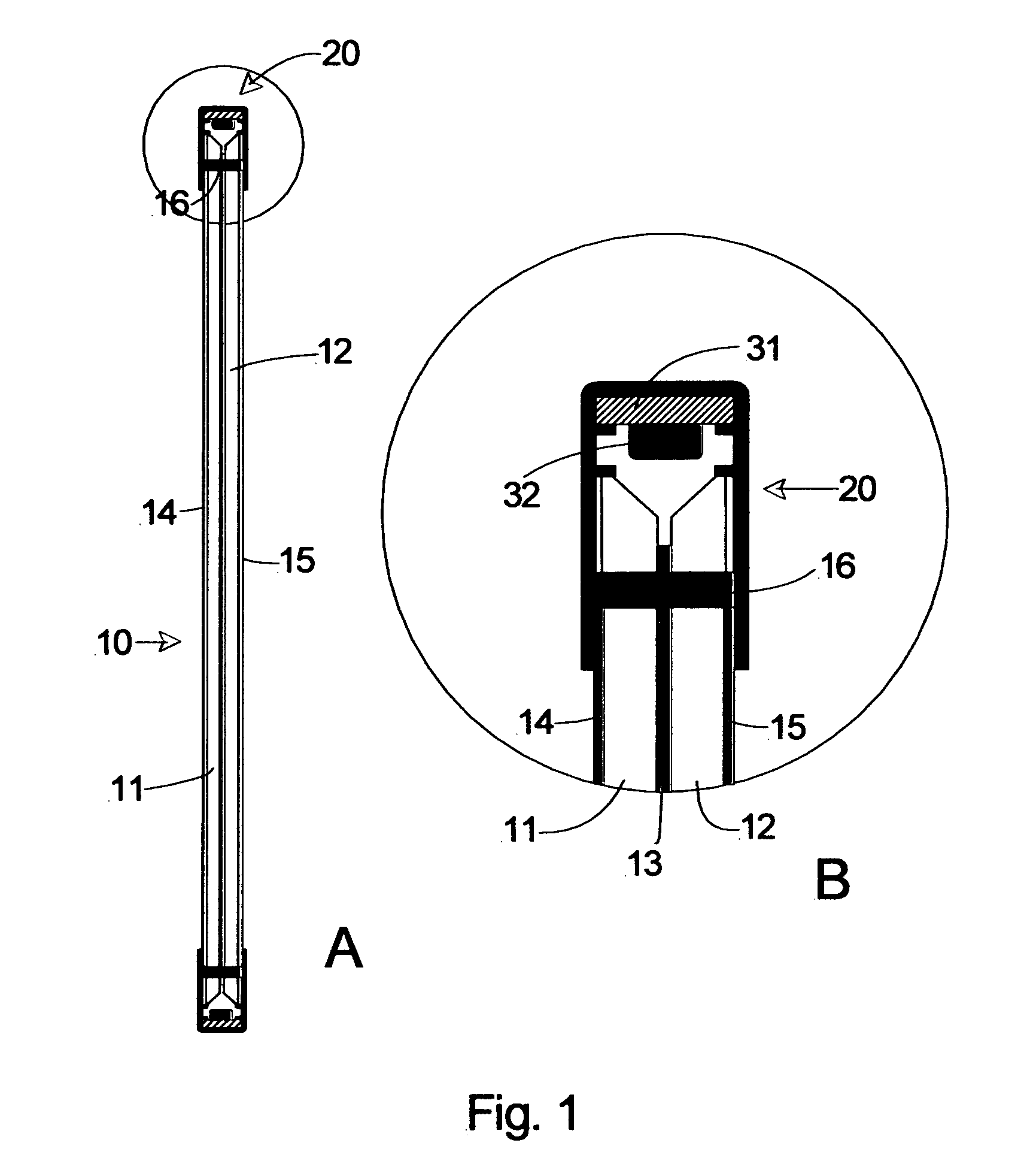
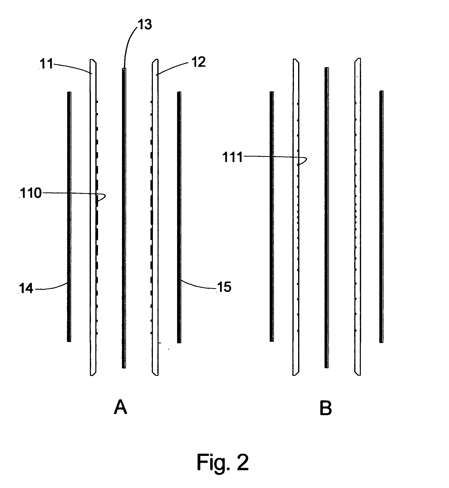
[0025]FIGS. 1, 2 and 3 illustrate a configuration of an illuminated signboard according to an embodiment of the present invention. Referring to FIGS. 1, 2 and 3, an opaque plate 13 having a high surface reflectivity is inserted between two flat light guide plates 11 and 12 and the light guide plates 11 and 12 and the opaque plate 13 are joined to each other by means of a plurality of screws 16 to form a single plate type secondary light source 10.

[0026]U-shaped frames 21, 22, 23 and 24 are combined with four sides of the plate type secondary light source 10 such that the plate type secondary light source 10 is surrounded by a frame housing 20. Transparent plates 14 and 15 including graphics or natural color pictures are attached to the exposed outer side of the plate type secondary light source 10.

[0027]PCBs 31 and LEDs 32 mounted on the surface of the PCBs 31 are mounted in the frame housing 20 such that light emitted from the LEDs 32 is inputted to inclined edges of the light guid...


PUM


Abstract

Disclosed herein is an illuminated signboard using a plane light source in which edges of two light guide plates are cut in an inclined form, an opaque plate having high surface reflectivity is inserted between the two light guide plates to optically block the two light guide plates from each other, and the light guide plates and the opaque plate are combined to form a second lighting part. U-shaped frames including LEDs are connected to construct a frame housing and the second lighting part is combined with the frame housing. Light emitted from the LEDs and transmitted in the light guide plates is dispersed by a dispersing mechanism formed on the backsides of the light guide plates using paint, print ink or engraving to transmit the light guide plates and graphics or natural color pictures formed on transparent plates attached to the outer sides of the light guide plates so as to illuminate the graphics or the natural color pictures.

Description

BACKGROUND OF THE INVENTION[0001]1. Field of the Invention[0002]The present invention relates to an illuminated signboard using a plane light source, and more particularly, to an illuminated signboard using a plane light source in which light emitting diodes (LEDs) are arranged at the edges of a transparent light guide plate and light emitted from the LEDs is effectively inputted to the light guide plate, transmitted according to repeated total reflection thereof, dispersed when colliding with a rough face or meeting the boundary of a reflecting face of the light guide plate and an alien material coated on the reflecting face and radiated in various directions so as to be used as a single light source.[0003]2. Background of the Related Art[0004]The principle of edge light is applied to a monitor light of a computer or various displays used in general stores, and edge lights have specific structures according to their purposes and uses and are used for various displays.[0005]For exam...

Claims


Application Information

Patent Timeline
IPC IPC(8): F21V21/00G09F13/18
CPCF21S4/006F21S8/032F21Y2101/02G02B6/003G02B6/0036G02B6/0043G02B6/0061G02B6/0076G09F13/18G09F13/22F21S4/24F21Y2115/10G09F2013/1854G09F2013/222Y10S362/80
Inventor JUNG, HAE-RYONG JUNG
Owner JUNG HAE RYONG JUNG
Learn More