Eureka AIR delivers breakthrough ideas for toughest innovation challenges, trusted by R&D personnel around the world.

Apparatus and methods for delivering fasteners during valve replacement

a technology of applicator and valve, applied in the direction of surgical staples, applications, manufacturing tools, etc., can solve the problems of reducing the patient's oxygen level, creating non-physiological blood flow dynamics, and increasing the risk of long-term or even permanent health damag

Active Publication Date: 2009-02-05
MEDTRONIC INC
View PDF48 Cites 196 Cited by
  • Summary
  • Abstract
  • Description
  • Claims
  • Application Information

AI Technical Summary

Benefits of technology

The present invention provides apparatus and methods for fastening devices to tissue and other devices during heart valve replacement. The invention includes a fastener delivery tool that can securely hold and release fasteners for securing a prosthesis to surrounding tissue. The tool has features for releasably engaging the fasteners in a relaxed state and a retaining member for limiting movement of the fasteners. The tool also includes a belt assembly carrying a plurality of fasteners and a pusher member for advancing the fasteners from the belt. The invention allows for fast and safe heart valve replacement procedures.

Problems solved by technology

This procedure is time consuming as doctors often use three to ten knots per suture.
During heart valve replacement procedures, the patient may be on cardiopulmonary bypass (CPB), which may reduce the patient's oxygen level and / or create non-physiological blood flow dynamics.
The longer a patient is on CPB, the greater the risk for long-term or even permanent health damage.
Existing suturing techniques extend the duration of CPB and, consequently, increase the health risks due to the patient.
Sewing rings can also be tedious and time consuming to secure to a valve orifice.
To assemble multiple component heart valves, for example, one component has to be sewn into another in vivo, resulting in a complex and time consuming process.
The complexity of the procedure also provides a greater opportunity for mistakes and requires a patient to be on cardiopulmonary bypass for a lengthy period.

Method used


Image

  • Apparatus and methods for delivering fasteners during valve replacement
  • Apparatus and methods for delivering fasteners during valve replacement
  • Apparatus and methods for delivering fasteners during valve replacement

Examples


Embodiment Construction

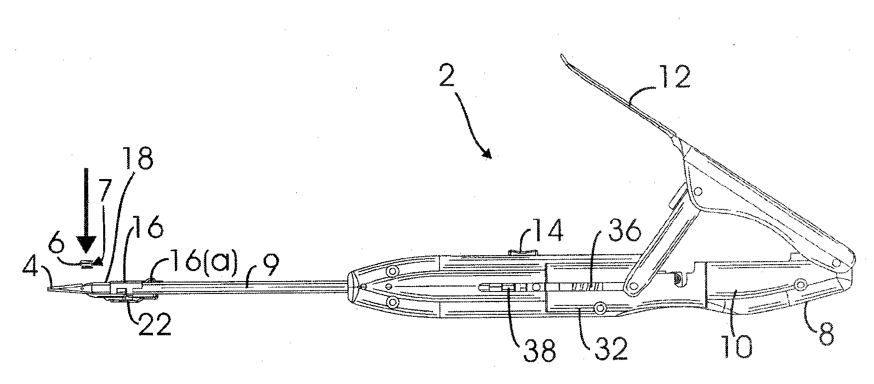
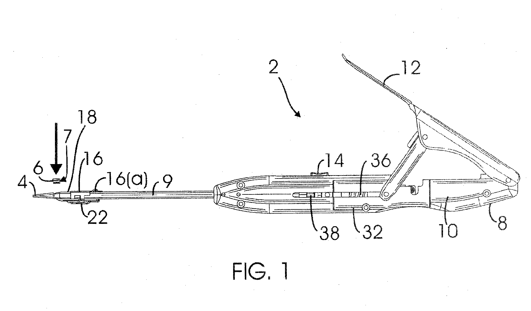
[0074]Turning to the drawings, FIG. 1 shows a first embodiment of a fastener delivery tool 2. The fastener delivery tool 2 includes a distal tip 4 or snout from which one or more fastener(s) 6 (described in more detail below) may be ejected and a proximal end 8 that may be grasped by a user during positioning and / or delivery of the fastener 6. The distal tip 4 and proximal end 8 of the tool 2 are separated by an elongated shaft 9. The fastener 6 may be stored within a cartridge 7 that may be loaded into the fastener delivery tool 2. The fastener delivery tool 2 also includes a proximally located handle 10 having a lever 12 or other actuator that may be used to deploy the fastener(s) 6. The handle 10 may be ergonomically shaped such that a user may easily manipulate the fastener delivery tool 2 into position. The handle 10 preferably includes a spring-biased trigger 14, e.g., a depressible button that may be used to eject the fastener 6 from the distal tip 4 of the tool 2.

[0075]A car...


PUM

PropertyMeasurementUnit
lengthsaaaaaaaaaa
lengthsaaaaaaaaaa
lengthsaaaaaaaaaa

Abstract

A fastener delivery tool includes a belt including pairs of features for releasably engaging tines of respective fasteners in a relaxed state defining a loop. The tool includes a loading chamber for receiving a fastener from the belt, a retaining member for limiting movement of the fastener within the loading chamber, an ejection track communicating with the loading chamber, a handle including an actuator, and a tongue and pusher member coupled to the actuator. Activation of the actuator advances the tongue to transform the fastener from the relaxed state to a U-shaped constrained state, and advances the pusher member to direct the fastener from the loading chamber down the ejection track. The tool may include a trigger for ejecting the fastener completely from the ejection track. The fastener may be used to secure a prosthetic heart valve or components thereof into surrounding tissue, e.g., within a tissue annulus.

Description

RELATED APPLICATION DATA[0001]This application claims benefit of co-pending provisional application Ser. No. 60 / 916,283, filed May 5, 2007, the entire disclosure of which is expressly incorporated by reference herein.FIELD OF THE INVENTION[0002]The invention relates generally to apparatus and methods for fastening devices to tissue or other devices, and, more particularly, to apparatus and methods for delivering fasteners during heart valve replacement, placement of other prostheses, or repair of body organs in general and vascular surgery, such as wound closure, anastomosis, hernia repair, and grafting procedures for aneurysm repair.BACKGROUND[0003]Prosthetic heart valves have been used to replace defective human valves in patients. A prosthetic valve generally includes a sewing ring or suture cuff that may be attached to and / or extend around a valve member. The sewing ring may be made from a biocompatible fabric and / or other material through which a needle and suture may pass. The...

Claims


Application Information

Patent Timeline
Patent Type & Authority Applications(United States)
IPC IPC(8): A61B17/08
CPCA61B17/00234A61B17/064A61B17/0684A61B17/1222A61F2/2409A61B2017/00473A61B2017/0053A61B2017/00544A61B2017/00862A61B17/1227
Inventor INO, TAKASHI HARRYDREWS, MICHAEL J.GURSKIS, DONNELL W.KNAB, JR., DWIGHT J.
Owner MEDTRONIC INC
Why Eureka
Eureka Blog
Learn More