Multi-carrier communication device and multi-carrier communication method
a communication device and multi-carrier technology, applied in the direction of wireless commuication services, pulse techniques, assess restrictions, etc., can solve the problems of deteriorating throughput deteriorating reception quality of the mobile station apparatus forced to perform handover, so as to prevent the throughput of other mobile station apparatuses from deteriorating
- Summary
- Abstract
- Description
- Claims
- Application Information
AI Technical Summary
Benefits of technology
Problems solved by technology
Method used
Image
Examples
embodiment 1
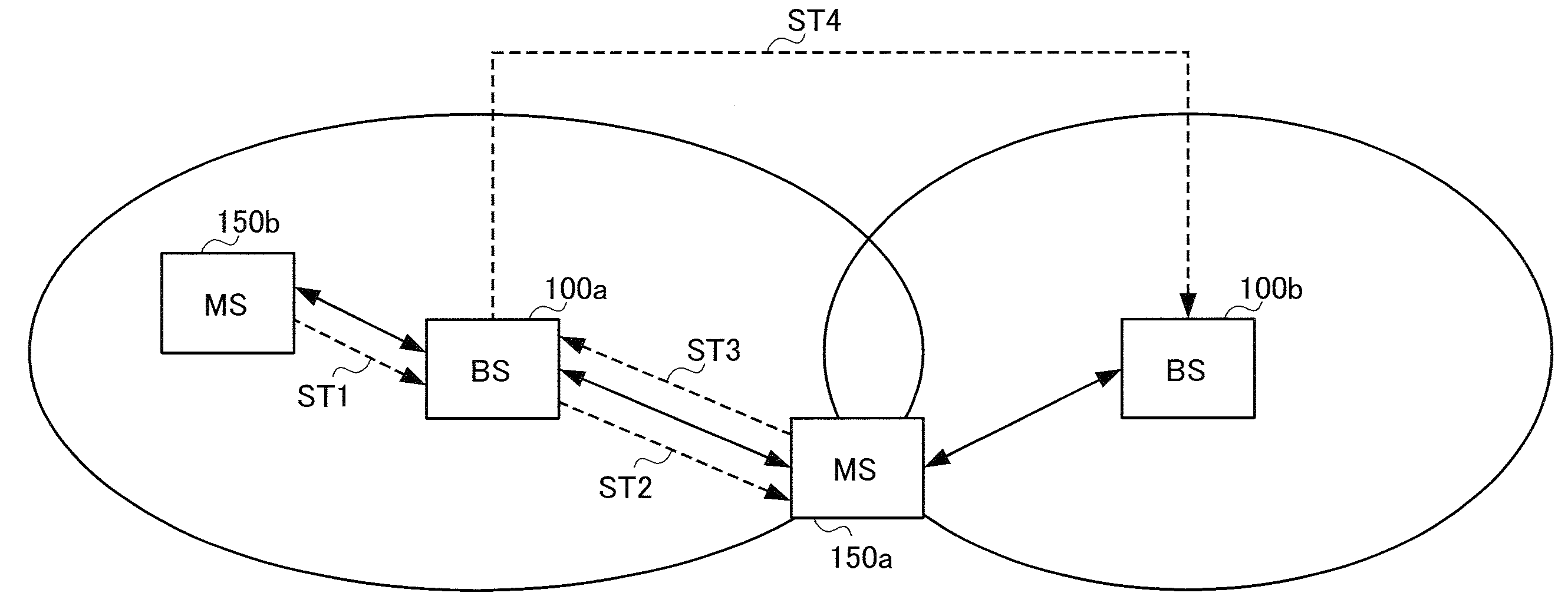
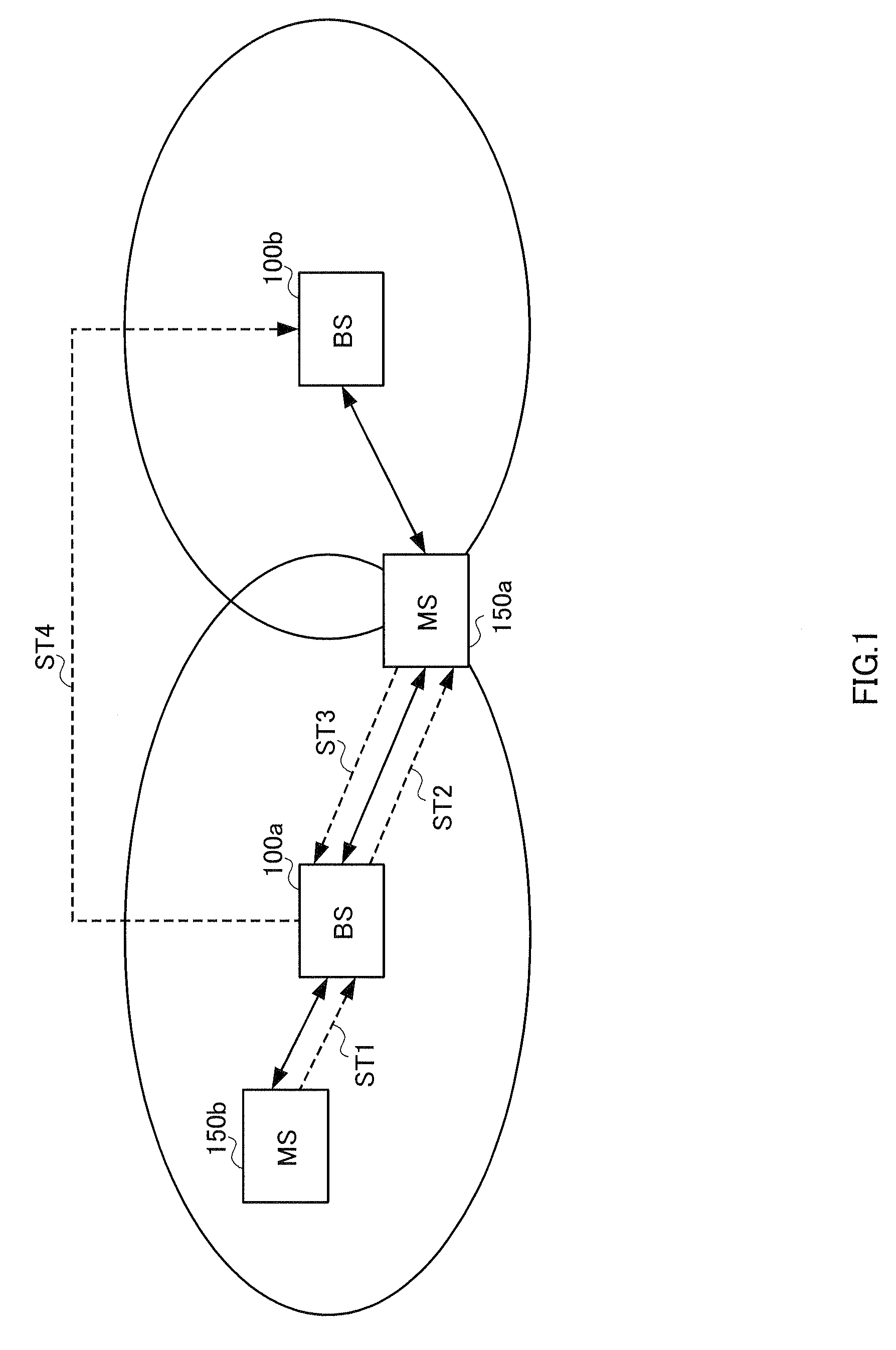
[0033]FIG. 1 shows the configuration of a cellular system according to Embodiment 1 of the present invention. The cellular system in FIG. 1 has base station apparatuses (BS) 100a and 100b arranged in two mutually neighboring cells.
[0034]This embodiment will explain a case as an example where MS150b located in a cell of BS100a starts a communication with BS100a while mobile station apparatus (MS) 150a located in the vicinity of a boundary between the two cells is communicating with BS100a.
[0035]The configurations of BS100a and MS150a will be explained below in order. Preferably, BS100b has the same configuration as BS100a. MS150b has the same configuration as MS150a.
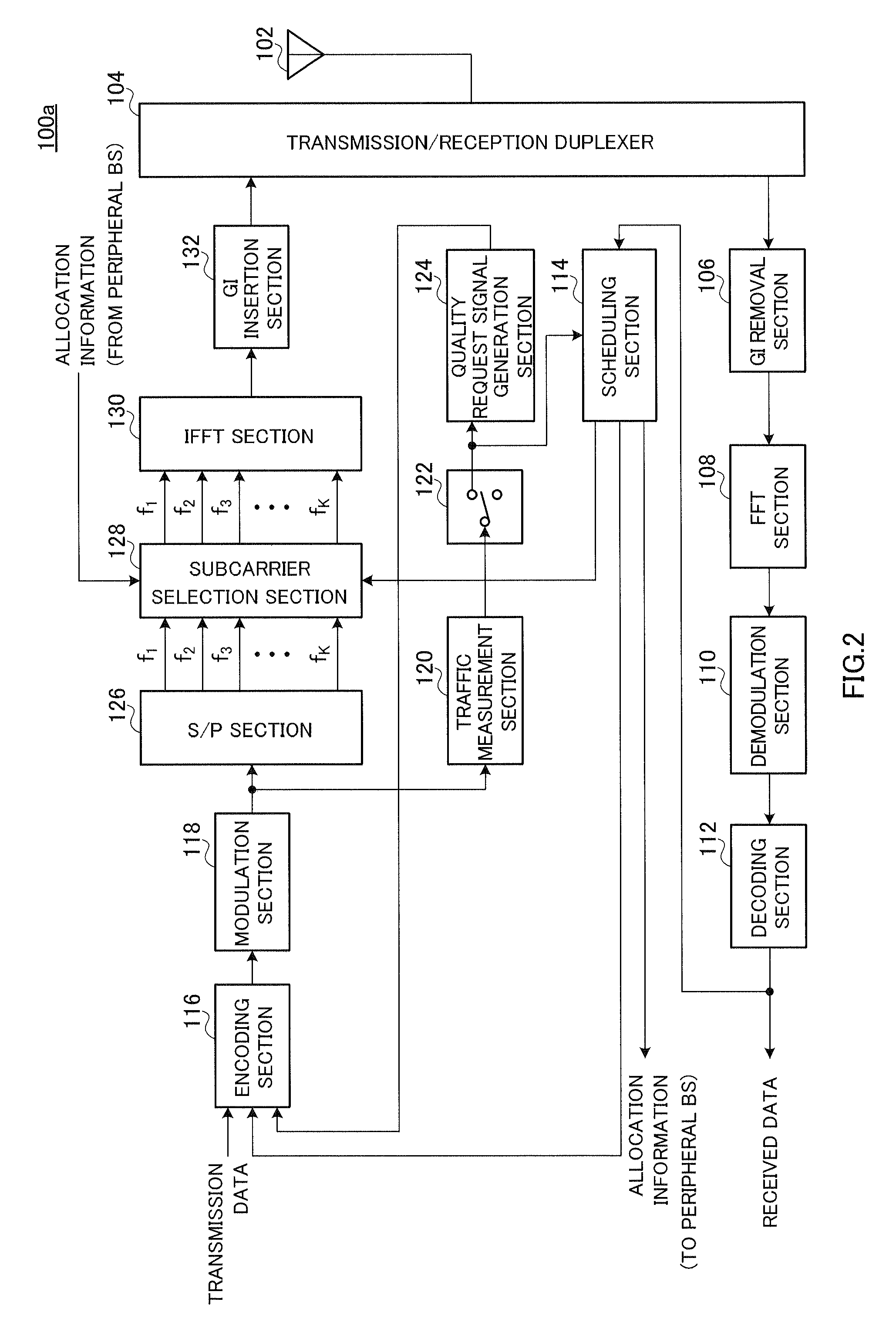
[0036]As shown in FIG. 2, BS100a has antenna 102, transmission / reception duplexer 104, GI (Guard Interval) removal section 106, FFT (Fast Fourier Transform) section 108, demodulation section 110, decoding section 112, scheduling section 114, encoding section 116, modulation section 118, traffic measuring section 120, sw...
embodiment 2
[0081]Embodiment 2 of the present invention will be explained below. The configurations of the cellular system, BS and MS according to this embodiment are the same as explained in Embodiment 1, and therefore explanations of the respective configurations will be omitted. This embodiment differs from Embodiment 1 only in the operation steps at scheduling section 114 executed to realize the operation (steps ST1 to 4) of the cellular system explained in Embodiment 1.
[0082]To realize the above described operation in the cellular system, scheduling section 114 of BS100a operates according to the steps which will be explained below. FIG. 6 is a flowchart illustrating an example of the operation steps of scheduling section 114.
[0083]First, steps ST10 to 40 explained in Embodiment 1 are executed.
[0084]In step ST51 following step ST40, quality difference Dij is calculated which corresponds to subcarrier pair Pij comprised of subcarriers fi and fj. Quality difference Dij can express how good t...
embodiment 3
[0092]Embodiment 3 of the present invention will be explained below. The configurations of the cellular system, BS and MS according to this embodiment are the same as explained in Embodiment 1, and therefore explanations of the respective configurations will be omitted. This embodiment differs from Embodiment 1 only in the operation steps of scheduling section 114 executed to realize the operation (steps ST1 to 4) of the cellular system explained in Embodiment 1.
[0093]Scheduling section 114 of BS100a operates according to the steps which will be explained below to realize the above described operation in the cellular system. FIG. 8 is a flowchart illustrating an example of the operation steps of scheduling section 114.
[0094]First, scheduling section 114 executes steps ST10 to 40 explained in Embodiment 1.
[0095]In step ST41 following step ST40, two groups A and B are formed. Group A is formed with the allocatable subcarriers having the same frequencies as any one of allocated subcarr...
PUM
 Abstract
Description
Claims
Application Information
 - R&D
- Intellectual Property
- Life Sciences
- Materials
- Tech Scout
- Unparalleled Data Quality
- Higher Quality Content
- 60% Fewer Hallucinations
Browse by: Latest US Patents, China's latest patents, Technical Efficacy Thesaurus, Application Domain, Technology Topic, Popular Technical Reports.
© 2025 PatSnap. All rights reserved.Legal|Privacy policy|Modern Slavery Act Transparency Statement|Sitemap|About US| Contact US: help@patsnap.com


