
Optical film and method for producing the same

a technology of optical film and heat shrinkage, applied in the field of optical film, can solve the problems of low heat shrinkage required for optical film for low heat shrinkage, inability to completely remove distortion, and inability to obtain low heat shrinkage, etc., to achieve low heat shrinkage, excel in dimensional stability, and low heat shrinkage

Inactive Publication Date: 2009-02-05
FUJIFILM CORP
View PDF1 Cites 21 Cited by
  • Summary
  • Abstract
  • Description
  • Claims
  • Application Information

AI Technical Summary

Benefits of technology

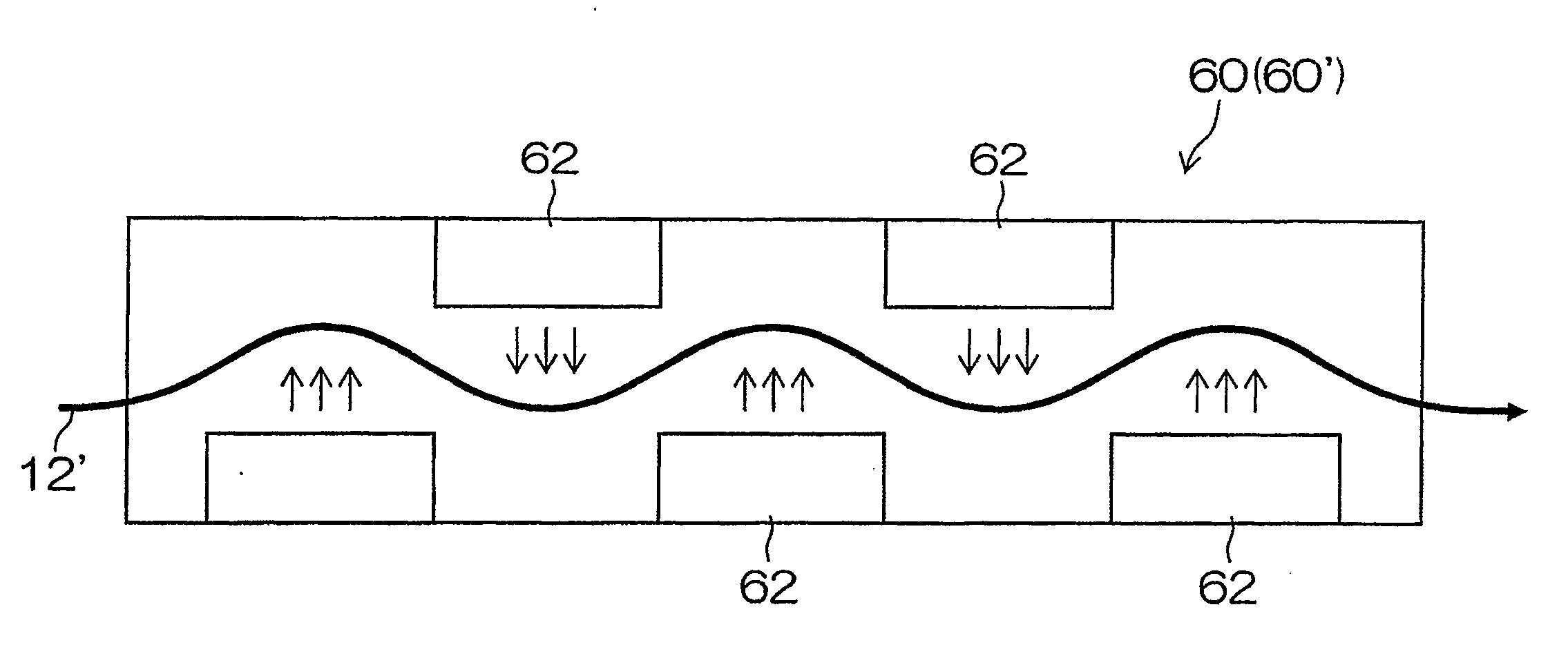
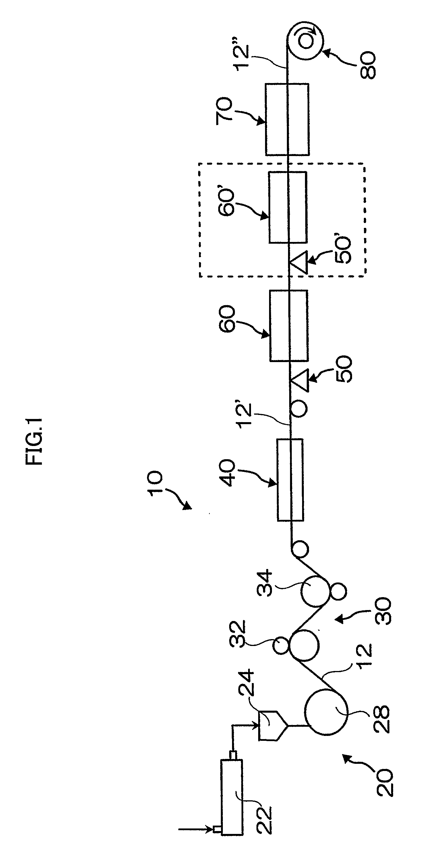
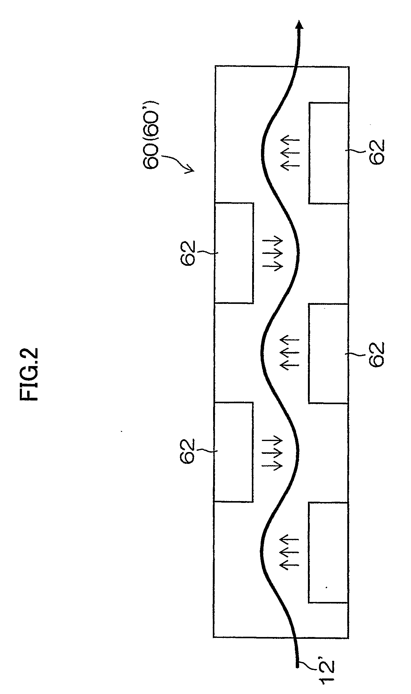
[0007]The inventor of the present has extensively studied based on the aforementioned problems, and, as a result, they have found that the heat shrinkage of the film can be particularly reduced by conducting the heat treatment comprising carrying the thermoplastic resin sheet prepared by biaxial stretching in the heated atmosphere, and / or conducting the heat treatment comprising carrying the sheet while bringing the sheet into contact with the heating roller.
[0027]According to the present invention, the optical film having low heat shrinkage can be produced. Therefore, the quality of members such as an antireflective film which uses the optical film produced by the present invention can be enhanced.

Problems solved by technology

However, although the amount of the heat shrinkage is reduced according to the temperature of the heat treatment in Japanese Patent Application Laid-Open No. 8-132523, the distortion cannot be completely removed, and unfortunately the heat shrinkage remains.
Also, the low heat shrinkage required for the optical film required for low heat shrinkage has not been obtained.

Method used


Image

  • Optical film and method for producing the same
  • Optical film and method for producing the same
  • Optical film and method for producing the same

Examples


examples

[0068]Hereinafter, the present invention will be described in further details with reference to Examples. However, the present invention is not limited thereto.

[0069]A polyethylene terephthalate (hereinafter, described as PET) resin having an intrinsic viscosity of 0.66 was produced by polycondensation using Ge as a catalyst. The PET was dried so that the water content was set to 50 ppm or less, and was melted in an extruder of which the heater temperature was set to 280 to 300° C. The melted PET resin was discharged on a chill roll electrostatically applied from a die part to obtain an amorphous base. After the obtained amorphous base was stretched by 3.3 times in the base travelling direction, the amorphous base was stretched by 3.8 times in the transverse direction to obtain a biaxially stretched film (optical film) having a thickness of 100 or 175 μm.

experiment 1

[Experiment 1]

[0070]The above PET base having a thickness of 100 or 175 μm was carried at a carrying speed of 105 m / min. A film which was not subjected to a heat treatment (described as A step in Table 1) by carrying the PET base in the heated atmosphere and a heat treatment (described as B step in Table 1) by carrying the PET base while bringing the PET base into contact with the heating roller, and a film which was subjected to the A step and / or B step according to the present invention were obtained. The heat shrinkage and flatness of the film in the MD direction and the TD direction were investigated. The tension of the film in the A step was 48 N / m, and the atmosphere temperature was 180° C. The tension of the film in the B step was 143 N / m, and the temperature of the heating roller was 145° C.

[0071]The following measurement was conducted, and the results were shown in Table 1.

Heat shrinkage: based on JIS C-2318.

(1) Sample Bar: Five sheets was taken from a sample bar with a wid...


PUM

PropertyMeasurementUnit
Temperatureaaaaaaaaaa
Fractionaaaaaaaaaa

Abstract

It is an object of the present invention to provide an optical film having low heat shrinkage and a method for producing the same. A heat treatment (60) carrying a biaxially stretched film of a thermoplastic resin (12′) prepared by biaxial stretching in a heated atmosphere is conducted, and / or a heat treatment (70) carrying the biaxially stretched film while bringing the biaxially stretched film into contact with a heating roller (72) is conducted.

Description

TECHNICAL FIELD[0001]The present invention relates to an optical film, and a method for producing the same. Particularly, the present invention relates to an optical film which is excellent in heat dimensional stability and has very low heat shrinkage (hereinafter, referred to as low heat shrinkage), and a method for producing the same.BACKGROUND ART[0002]A thermoplastic resin film is produced by a melt film forming method. In the melt film forming method, a thermoplastic resin is melted in an extruder, and then extruded on a support, for example, a cooling drum from a die to form a thermoplastic resin film. The thermoplastic resin film formed by this method is usually biaxially stretched in a long (longitudinal) direction and in a wide (transverse) direction.[0003]By the way, the molecules of a biaxially stretched thermoplastic resin film are orientated by the stretching to enhance mechanical properties such as strength. However, since the distortion caused by the stretching remain...

Claims


Application Information

Patent Timeline
IPC IPC(8): B29D11/00B29C55/12G02B1/04
CPCB29C47/0021B29C47/887B29K2067/00B29C55/143B29C47/888B29C48/08B29C48/91B29C48/914B29C48/9165B29C48/9175Y10T428/31786
Inventor HIGASHI, SOUICHIRO
Owner FUJIFILM CORP
Learn More