Miniaturized Ion Mobility Spectrometer

Active Publication Date: 2009-02-05
RAPISCAN LAB
View PDF71 Cites 18 Cited by
  • Summary
  • Abstract
  • Description
  • Claims
  • Application Information

AI Technical Summary

Benefits of technology

[0029]By utilizing the combination of a unique electronic ion injection control circuit in conjunction with a particularly designed drift cell construction, the instantly disclosed ion mobility spectrometer achieves increased levels of sensitivity, while achieving significant reductions in size and weight. The instant IMS is of a much simpler and easy to manufacture design, rugged and hermetically sealed, capable of operation at high temperatures to at least 250° C., and is uniquely sensitive, particularly to explosive chemicals.
[0030]A unique ion reservoir is achieved in which ions are temporarily collected prior to injection into the drift region of the IMS. This feature increases the sampled ion population allowing more time for reactions between the reactant ions and sample molecules thus increasing the signal-to-noise parameter as well as over-all sensitivity to a given concentration of sample chemicals. This unique feature allows for better sensitivity while permitting smaller design geometries producing a relatively small device.
[0031]In order to achieve an efficient ion reservoir, an innovative electronic ion injection control circuit is provided that is much simpler than current designs for IMS. This circuit operates off of a low voltage trigger timing pulse which trips an opto-isolator. This device is part of an innovative resistive bridge circuit connected to a high voltage transistor. The trigger pulse to the opto-isolator causes the voltage to the base of the high voltage transistor to vary with the pulse. This allows the transistor to provide a sharp square wave voltage pulse to the ion control ring. The resultant large drop in voltage from the pulse causes the ions in the ion reservoir to be injected into the IMS drift region. Between pulses, the ion control ring is in a high voltage condition which stops the ions in the ion reservoir. This circuit, in a very simple and reliable way, enables the high voltage switching (typically between 800 and 1000 volts) to be accomplished, which permits the establishment of the ion reservoir described above.

Problems solved by technology

While the majority of current IMS designs rely on the use of ion control and screen grids to provide a uniform control voltage radially across the ion drift tube; the ion injection circuit as described above operates at sufficiently high voltages such that the use of these grids was found to be unnecessary in the unique IMS drift cell construction subsequently described.

Method used


Image

  • Miniaturized Ion Mobility Spectrometer
  • Miniaturized Ion Mobility Spectrometer
  • Miniaturized Ion Mobility Spectrometer

Examples


Embodiment Construction

Ion Mobility Spectrometry General Description, Operation, and Theory

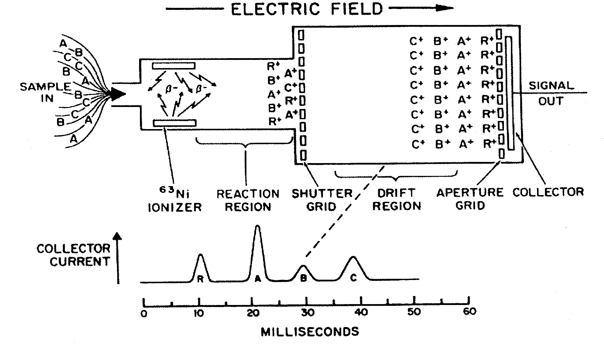
[0062]The IMS, while complex in many of its aspects is conceptually easy to describe. In general terms, it can be thought of as an electronic, gas phase, atmospheric pressure, trace chemical analyzer providing low picogram sensitivity for many chemicals with chemical discrimination based upon ion mobility. Structurally, it is simply an electric field drift tube with an ionizing source, a means for injecting the ions into the drift tube, and an ion collector that electrically measures the ions. In more detail, it is most easy to describe the structure and operation of a standard prior art IMS using a schematic diagram, as set forth in FIG. 1.

[0063]In the standard model of the IMS, the drift tube consists of a series of stacked cylindrical rings insulated from each other and ground. The rings are connected to each other in series to a resistive voltage divider, which when a high voltage is supplied, energizes each suc...


PUM


Abstract

By utilizing the combination of a unique electronic ion injection control circuit in conjunction with a particularly designed drift cell construction, the instantly disclosed ion mobility spectrometer achieves increased levels of sensitivity, while achieving significant reductions in size and weight. The instant IMS is of a much simpler and easy to manufacture design, rugged and hermetically sealed, capable of operation at high temperatures to at least 250° C., and is uniquely sensitive, particularly to explosive chemicals.

Description

REFERENCE TO RELATED APPLICATIONS[0001]This application claims benefit of the filing date of U.S. Provisional Patent Application No. 60 / 812,463, filed on Jun. 9, 2006, the contents of which are herein incorporated by reference.[0002]Certain aspects of this invention were made with Government support under contract numbers NAS2-03137 and NNA04CA08C awarded by NASA. The Government has certain rights in those aspects of the invention.FIELD OF THE INVENTION[0003]This invention relates to ion mobility spectrometry; particularly to ion mobility spectrometers having enhanced sensitivity and performance for the detection of trace chemicals; and most particularly to a highly sensitive and miniaturized Ion Mobility Spectrometer (IMS) incorporating a plurality of mechanical and electrical innovations, resulting in synergistic operability enhancements.BACKGROUND OF THE INVENTION[0004]The Ion Mobility Spectrometer was invented by Dr. Martin J. Cohen and others in the late 1960's at Franklin GNO ...

Claims


Application Information

Patent Timeline
IPC IPC(8): B01D59/44
CPCG01N27/622H01J49/00H01J49/0013H01J49/022
Inventor KAYE, WILLIAM J.STIMAC, ROBERT M.
Owner RAPISCAN LAB
Why Eureka
Try Eureka