
Wind turbine blade with deflectable flaps

a wind turbine and flap technology, which is applied in the direction of rotors, marine propulsion, vessel construction, etc., can solve the problems of limiting aerodynamic power capture, difficult to control the load of the blade, and the load of the rotor will exceed the limits set by the structural strength of the wind turbine, so as to prevent air gaps

Active Publication Date: 2009-01-29
GAMESA INNOVATION & TECH SA
View PDF7 Cites 51 Cited by
  • Summary
  • Abstract
  • Description
  • Claims
  • Application Information

AI Technical Summary

Benefits of technology

[0015]Another object of the invention is to provide a wind turbine having means for controlling the changes in the flow and hence optimizing the whole rotor performance and minimizing the pitch activity of the blades.
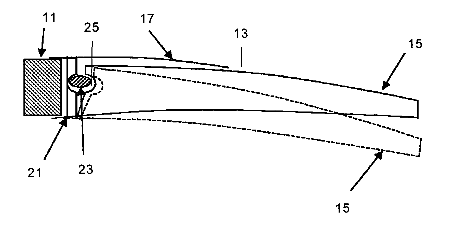
[0018]In a preferred embodiment said fluid inflatable means is a flexible tube extending along the flap spanwise direction which is arranged inside a chamber placed in a suitable position for deflecting the flap in the desired direction, i.e. in an upper position for deflecting the flap downwards and in an lower position for deflecting the flap upwards. Hereby a deflectable flap in one direction (upwards or downwards) it is achieved.
[0020]In another preferred embodiment the second component also includes a lower and / or upper fairing plate for preventing air gaps when the flap is deflected. Hereby an aerodynamically optimized deflectable flap is achieved.

Problems solved by technology

Otherwise, specially at high wind speeds, the load of the rotor will exceed the limits set by the wind turbine's structural strength.
In the “stall” control method the rotor blade's pitch angle is changed to a greater angle of attack to the point where the flow separates at the rotor blade's surface, thus limiting the aerodynamic power capture.
However, for large wind turbine blades it can be difficult to control the blade loading as the blade loading can vary over the blade length.
As the rotor size is increasing, the pitching of the blades not necessarily provides an optimized loading along the whole blade because nor only wind shear, yaw errors and gust will affect the flow on the blade, but different gusts can hit the blade simultaneously or complex wind shear profiles with negative wind shear can occur.
One disadvantage of Gurney flaps is the increase in aerodynamic noise from the free ends of the Gurney flaps and from the gaps in the blade where the Gurney flaps are positioned.
One disadvantage of the piezoelectric plates are the electrical cables that are necessary to bring power to them.
These cables are woundable to electrical lightning and can easily be damaged in case of a lightning strike.
None of these proposals produces fully satisfactory results, therefore a continuing need exists for wind turbines having rotor blades with means for reducing the blade loads.

Method used


Image

  • Wind turbine blade with deflectable flaps
  • Wind turbine blade with deflectable flaps

Examples


Embodiment Construction

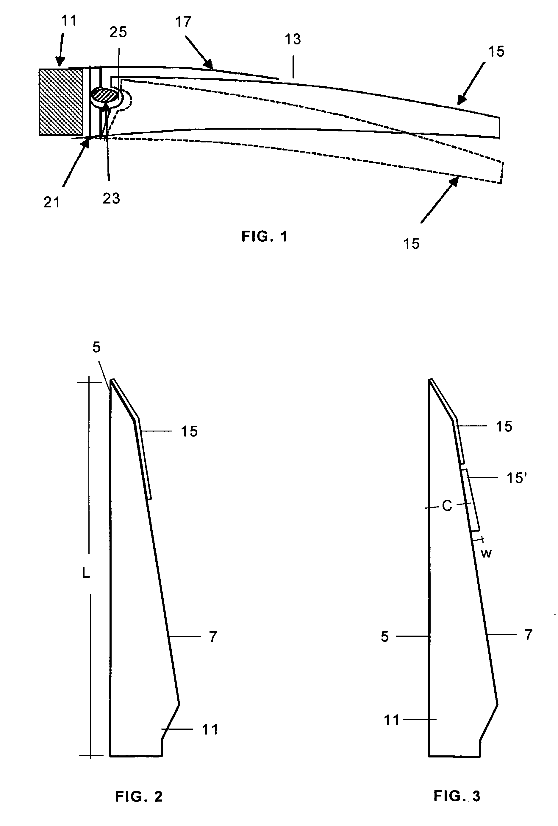
[0026]FIG. 1 shows the second component 13 attached to the first component 11 of a wind turbine blade according to a first embodiment of the present invention.

[0027]The first component 11 has a typical aerodynamic profile with a leading edge 5, a trailing edge 7 and suction and pressure sides between the leading edge 5 and the trailing edge 7.

[0028]The following detailed description will refer to an embodiment of the invention in which the second component 13 is attached to the trailing edge 7 of the first component 11. The invention also comprises an embodiment in which the second component 13 is similarly attached to the leading edge 5 of the first component 11.

[0029]In FIG. 1 it is only shown the end part of the trailing edge to which the second component 13 is attached.

[0030]The second component 13 includes a deflectable flap 15 and a fairing plate 17.

[0031]FIG. 1 illustrates a downwards deflection of flap 15 from a first position to a second position—in phantom lines—by means o...


PUM


Abstract

A wind turbine having at least a blade comprising a first component (11) having an aerodynamic profile with a leading edge, a trailing edge and suction and pressure sides between the leading edge and the trailing edge, and a second component (13), attached to the trailing edge and / or to the leading edge of the first component (11) in at least a part of the blade, comprising an upwards and / or downwards deflectable flap (15) that allows changing the flow over the blade, in which the means for deflecting the flap (15) are fluid inflatable means (23) placed in a flap inner chamber (25) close to the first component (11) and in which the wind turbine comprises means for controlling said inflatable means (23) depending on the wind situation and / or the blade loads.

Description

FIELD OF THE INVENTION[0001]The invention relates to a wind turbine having rotor blades with deflectable flaps and in particular to rotor blades with deflectable flaps for optimizing the blade loads.BACKGROUND[0002]Wind turbines are devices that convert mechanical energy to electrical energy. A typical wind turbine includes a nacelle mounted on a tower housing a drive train for transmitting the rotation of a rotor to an electric generator.[0003]The efficiency of a wind turbine depends on many factors. One of them is the orientation of the rotor blades with respect to the direction of the air stream, which is usually controlled by a pitch system that allows adjusting the pitch angle of the rotor blades for maintaining the rotor's speed at a constant value or within a given range. Otherwise, specially at high wind speeds, the load of the rotor will exceed the limits set by the wind turbine's structural strength.[0004]There are two basic methods for controlling the power of a wind turb...

Claims


Application Information

Patent Timeline
Patent Type & Authority Applications(United States)
IPC IPC(8): F03D7/00
CPCF03D1/0675F03D7/0232F03D7/0252Y02E10/723F05B2240/31F05B2240/311Y02E10/721F03D7/0256Y02E10/72F05B2240/3052F03D1/0608F03D7/0224
Inventor MELDGAARD, CHRISTIANFRIEDRICH, MICHAEL
Owner GAMESA INNOVATION & TECH SA
Learn More