
Diaphragm for loudspeaker and loudspeaker

a technology for loudspeakers and diaphragms, applied in the direction of transducer diaphragms, instruments, transducer details, etc., can solve the problems and affecting the sound quality of the high-range frequency range, so as to facilitate the manufacture of the product. , the effect of reducing the manufacturing tim

Inactive Publication Date: 2009-01-29
SAITO FUMIO +1
View PDF2 Cites 21 Cited by
  • Summary
  • Abstract
  • Description
  • Claims
  • Application Information

AI Technical Summary

Benefits of technology

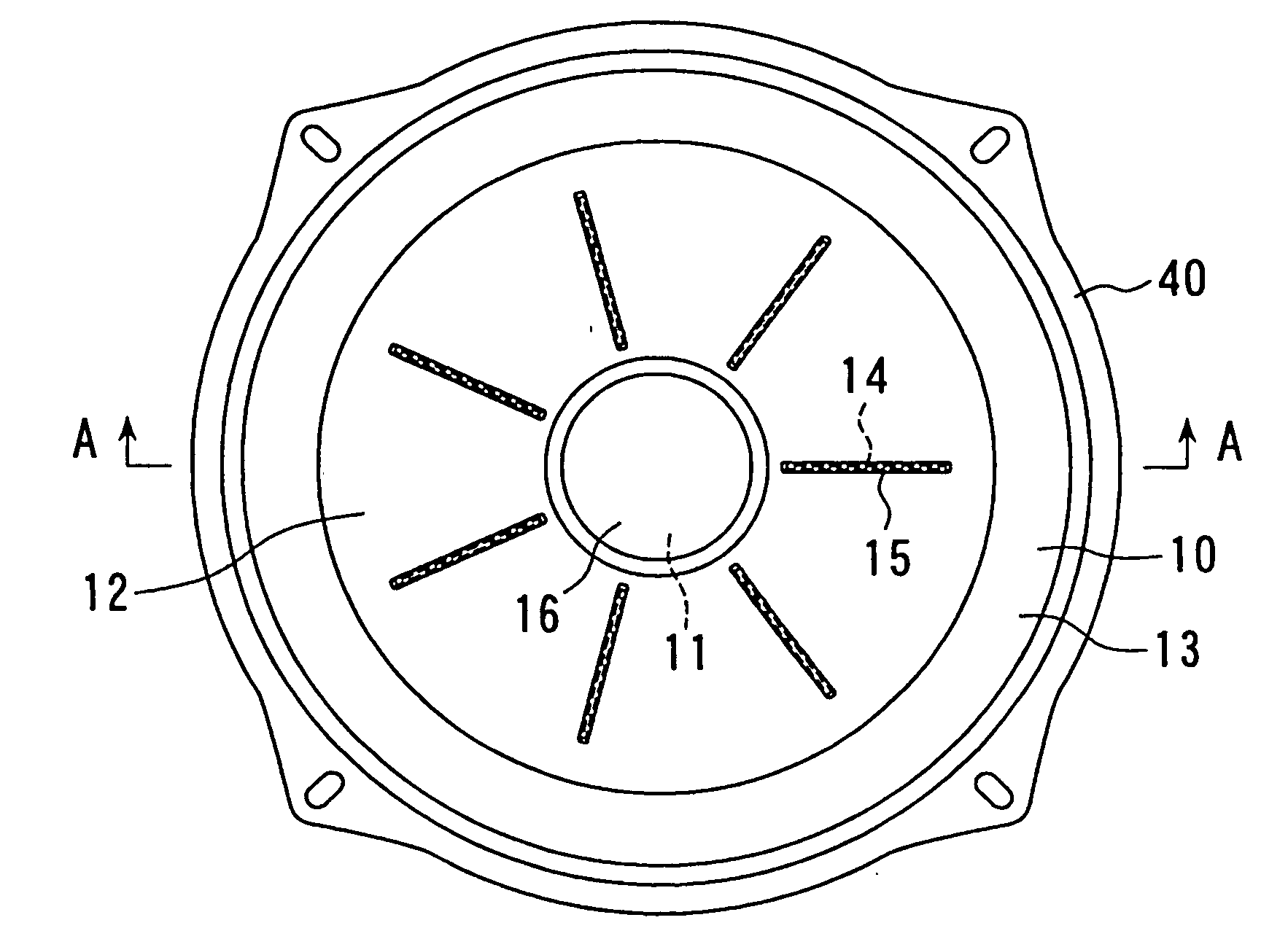
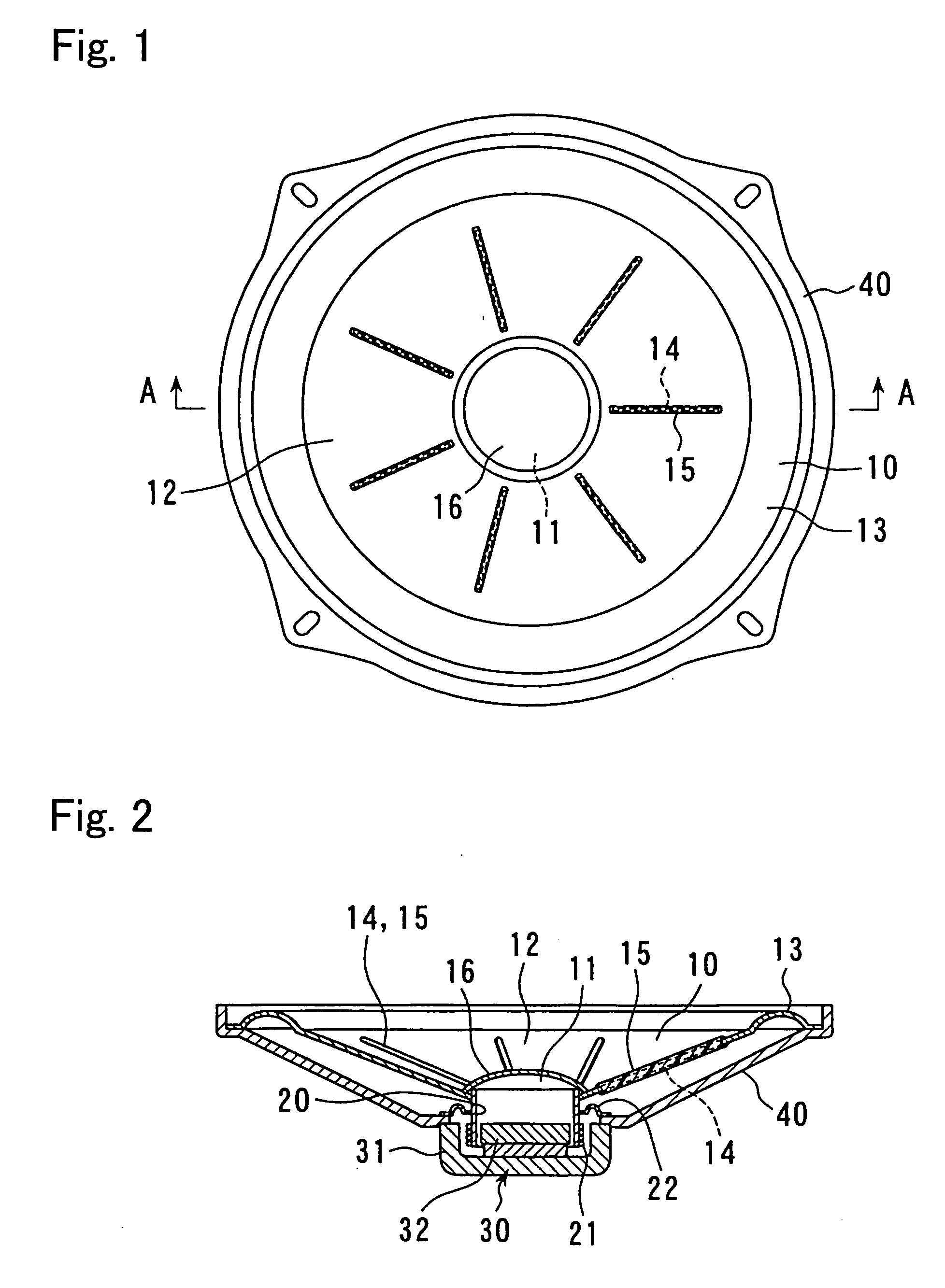
[0012]Since the slits 14, 14a are formed in this way so that the diaphragm body 12 is divided so as to disperse resonance spots, an axisymmetrical mode is not generated in a vibration mode of the diaphragm in a high range frequency, large peaks and dips in the high frequency range are reduced, and the frequency characteristic is smoothened. Therefore, a smooth frequency characteristic can be obtained from a low range to the high range, which makes the sound quality favorable.
[0014]Since the slits 14, 14a are formed in the linear shape or curved shape in this way in the present invention, formation is easier than conventional examples in which a large number of damping holes are formed, the filling material 15 can be filled in easily, by which manufacture is facilitated in the entirety.
[0015]Also, the diaphragm for a loudspeaker of the present invention uses a material with a smaller Young's modulus and / or a larger internal loss than those of a main material of the diaphragm body 12 as the filling material 15. By this, the resonance of the axisymmetrical mode can be absorbed and dispersed. In here, if a porous material such as foaming material or porous rubber is used as the filling material 15, since they have air layers, and thus, large internal losses, the resonance of the axisymmetrical mode can be absorbed and dispersed, which can make sound quality favorable.
[0017]By using such thermoplastic resin, manufacturing time can be reduced, which is appropriate for mass production, and manufacture itself is facilitated.
[0018]Also, in the loudspeaker according to the present invention, a coil bobbin 20 having a voice coil 21 is provided at a center part on the back face of a diaphragm 10 for a loudspeaker, and this coil bobbin 20 is supported to be capable of vibration while the voice coil 21 is arranged in a magnetic gap of a magnetic circuit 30. And, the diaphragm 10 is provided on its outer circumference with an edge 13 through which the diaphragm 10 is supported by a frame 40 in construction. According to this loudspeaker, since the diaphragm 10 in the above construction is provided, its frequency characteristics are smooth over the entire region.

Problems solved by technology

However, if a main material of a diaphragm body is made of a single material such as pulp, for example, it is well known that vibration modes at high range frequencies become axisymmetrical.
In this case, large peaks and dips are generated in the high range side, and the sound quality is not favorable.
However, with this prior art, since the large number of damping holes should be provided in the diaphragm, manufacture is complicated, and drop of rigidity of the diaphragm due to the large number of damping holes is not preferable.
Also, a work to uniformly fill the damping compound in the large number of damping holes is required, which results in a disadvantage that manufacture is complicated in this point.

Method used


Image

  • Diaphragm for loudspeaker and loudspeaker
  • Diaphragm for loudspeaker and loudspeaker
  • Diaphragm for loudspeaker and loudspeaker

Examples


embodiment 1

[0062]As a sixth preferred embodiment of the present invention, while the diaphragm material as well as the shape, number and dimension of the slits 14 are the same as those in the preferred embodiment 1, a thermoplastic resin with smaller Young's modulus and larger internal loss than those of the constitutional material of the diaphragm, respectively, is used as the filling material 15 to be filled in the slits 14. This resin is applied to cover at least one of the diaphragm surfaces in a film state under heating and also filled in the slits 14 so as to make the diaphragm 10, and a loudspeaker is constituted with the other constructions unchanged. The frequency characteristic diagram of this loudspeaker is shown in FIG. 13. The remarkable peaks and dips in a high range are reduced as compared with FIG. 15 of a conventional example, and sound quality can be improved. Since the resin is applied on the surface of the diaphragm in this example, the strength of the diaphragm can be impr...

embodiment 5

[0067]Also, use of porous rubber as the filling material 15 to be filled in the slits is exemplified in the preferred embodiment 5, but it may be a foaming material. Since foaming materials and porous materials have fine air layers inside, their internal losses are large enough to absorb and disperse the resonance, which is preferable.

[0068]As the filling material 15 to be used in the present invention, those with smaller Young's modulus and / or larger internal loss than those of a main material of the diaphragm body 12 are used.

[0069]An example produced by using pulp as a main material for the diaphragm body 12 has been described, but a metal diaphragm using aluminum or magnesium or a diaphragm made of plastic may be used.


PUM


Abstract

A diaphragm body (12) is provided with a plurality of slits (14, 14a) extending from the central part thereof toward the outer circumference. The slits (14, 14a) are filled with a low-elasticity filling material composed of a material different from that of the diaphragm body (12). The slits (14, 14a) are extended rectilinearly or curvedly. The filling material (15) has a Young's modulus lower than that of the principal material of the diaphragm body (12) and / or an internal loss larger than of the principal material of the diaphragm body (12). Furthermore, the filling material (15) employs UV ray and / or visible ray curable resin or thermoplastic resin. Alternatively the filler (15) may be a porous material or a foamed material. The diaphragm body (12) produced by filling the slits (14, 14a) with the filling material (15) is employed for constituting a loudspeaker.

Description

RELATED APPLICATIONS [0001]This application is a national stage application under 35 USC 371 of international application PCT / JP2004 / 018283 filed Dec. 8, 2004, which claims priority from Japan application 2004-15079 filed Jan. 23, 2004.TECHNICAL FIELD [0002]The present invention relates to a diaphragm for a loudspeaker in acoustic equipment and a loudspeaker, and particularly to a diaphragm which prevents generation of axisymmetrical mode in a vibration mode of a diaphragm in a high range frequency, reduces peaks and dips in a high range, and smoothens frequency characteristics from a low range to the high range to realize favorable sound quality and a loudspeaker using this diaphragm.BACKGROUND ART [0003]A diaphragm for a loudspeaker is required to have a smooth frequency characteristic from a low range to a high range.[0004]However, if a main material of a diaphragm body is made of a single material such as pulp, for example, it is well known that vibration modes at high range fre...

Claims


Application Information

Patent Timeline
Patent Type & Authority Applications(United States)
IPC IPC(8): H04R11/02H04R7/00H04R9/06H04R9/02H04R7/02H04R7/12H04R7/14H04R9/04
CPCH04R9/06H04R7/12H04R7/14H04R9/04H04R31/006
Inventor SAITO, FUMIOMIKUNIYA, TAKASHI
Owner SAITO FUMIO
Learn More