
Ac-dc converter

a converter and converter technology, applied in the direction of electric variable regulation, process and machine control, instruments, etc., can solve the problems of limiting the improvement of conversion efficiency of the power unit, the electric power consumption of the high-speed printer is apt to increase, and the conventional ac-dc converter cannot cope with a load exceeding 1282, so as to achieve a higher peak power

Inactive Publication Date: 2009-01-29
SANKEN ELECTRIC CO LTD
View PDF2 Cites 37 Cited by
  • Summary
  • Abstract
  • Description
  • Claims
  • Application Information

AI Technical Summary

Benefits of technology

[0010]Under the above-mentioned situation, an object of the present invention is to provide an inexpensive AC-DC converter capable of acquiring an electrical power through a normal plug outlet of the commercial power source and also coping with a higher peak power on the side of an electrical load.

Problems solved by technology

In other words, it means that the conventional AC-DC converter cannot cope with an electrical equipment (load) consuming a power exceeding 1282.
This electric power consumption in the high-speed printer is apt to get larger as the printing speed is increased.
However, it should be noted that there is a limit in the improvement of conversion efficiency of the power unit and therefore, the attempt of increasing a power to be picked up is saturated recently.
For speeding up of the printer in spite of the above situation, there would be required an exclusive commercial plug outlet or an installation for picking up a power through biserial commercial power lines, causing an increasing of troublesome tasks and the AC-DC converter to be expensive.

Method used


Image

  • Ac-dc converter
  • Ac-dc converter
  • Ac-dc converter

Examples


first embodiment

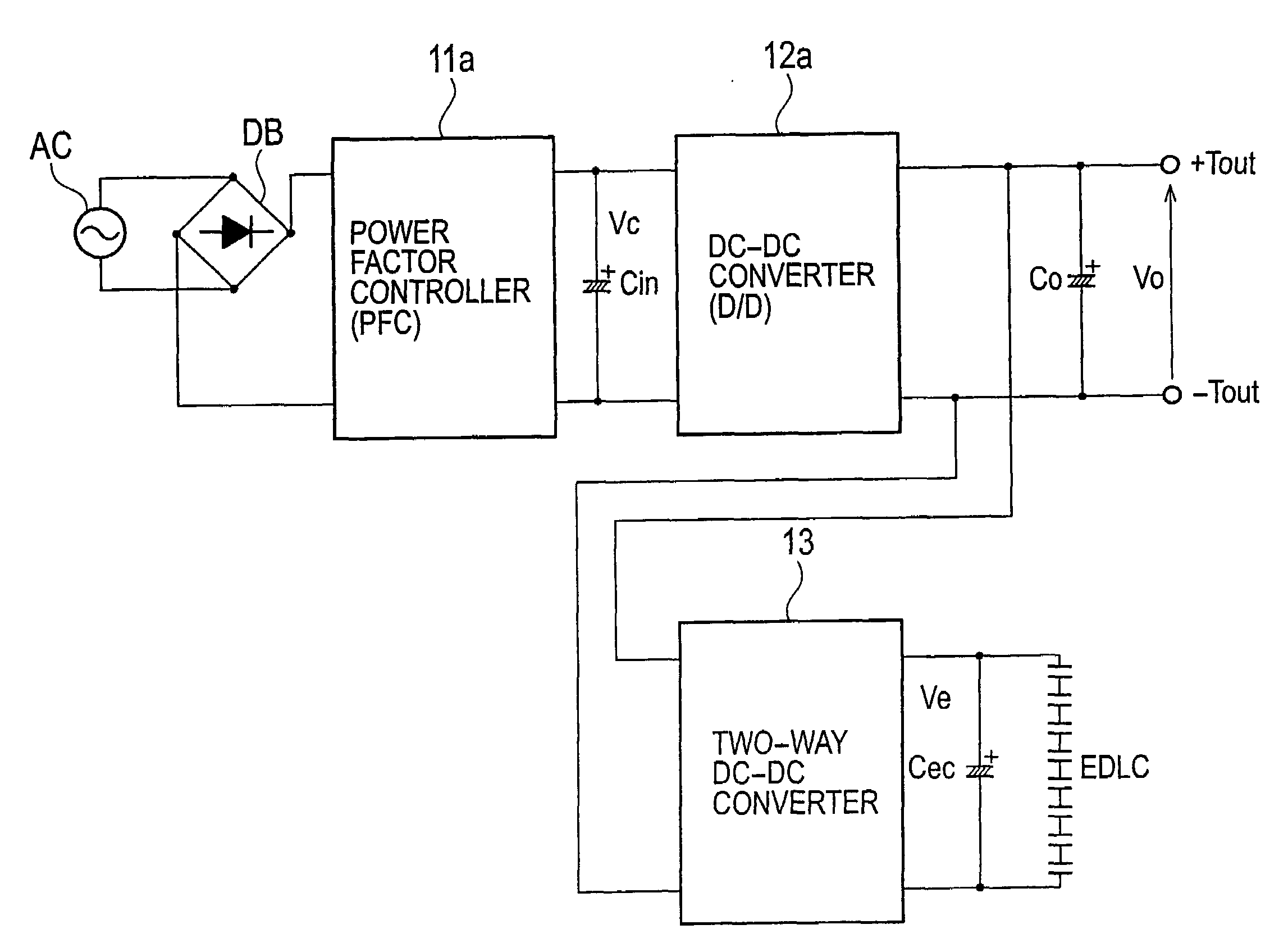
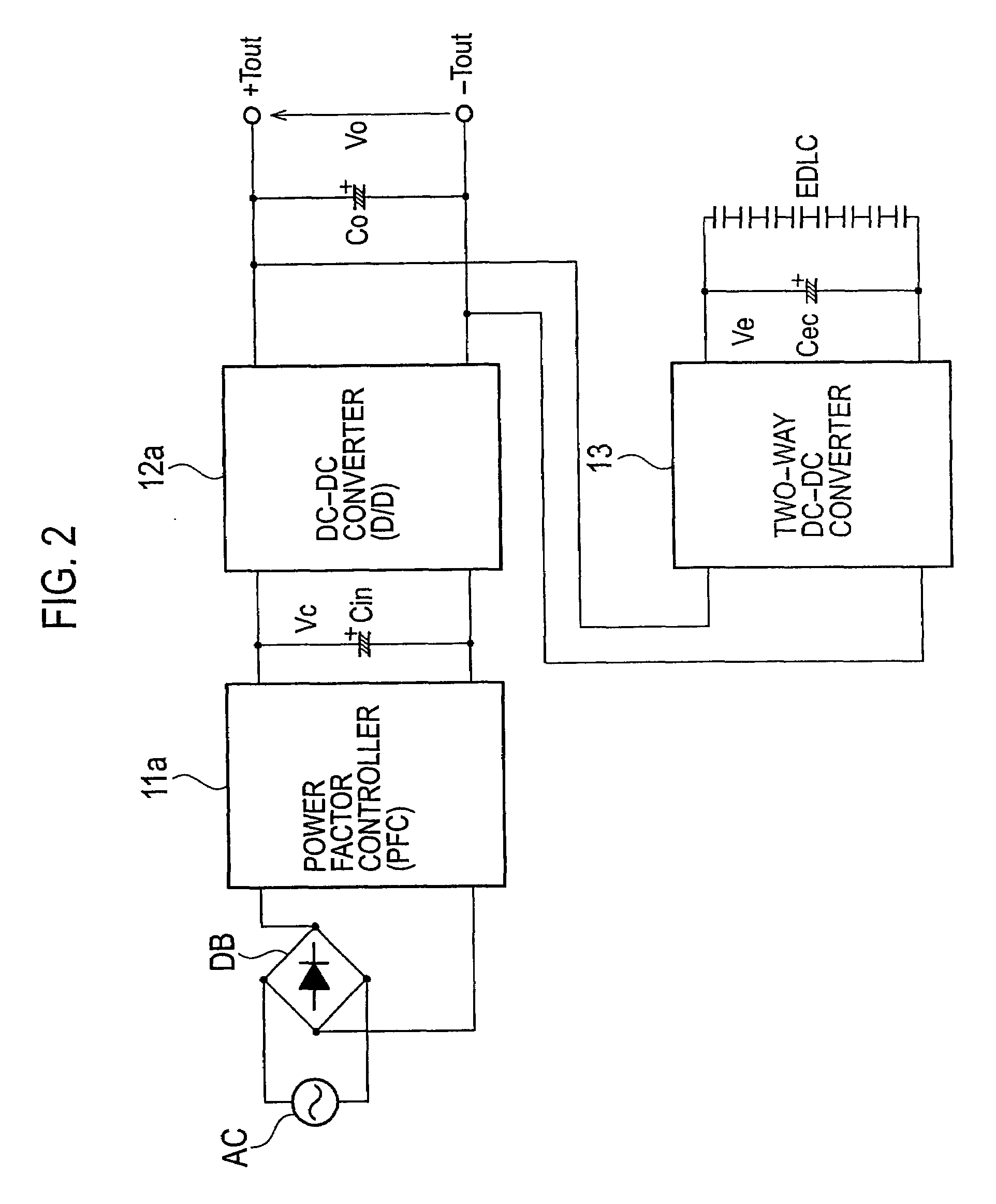
[0025]FIG. 2 is a view showing the constitution of an AC-DC converter in accordance with the present invention. Note, elements identical to constituents of the conventional AC-DC converter of FIG. 1 are indicated with the same reference numerals respectively and further, their overlapping descriptions are eliminated.

[0026]Besides the constituents of the conventional AC-DC converter of FIG. 1, the AC-DC converter of the first embodiment further includes an output capacitor Co, a two-way DC-DC converter 13, a smoothing capacitor Cec and an electric double layer capacitor EDLC. Again, the AC-DC converter includes a power factor controller 11a and a DC-DC converter 12a in place of the power factor controller 11 and the DC-DC converter 12 of the conventional converter, respectively.

[0027]The output capacitor Co is connected between output terminals of the DC-DC converter 12a. Both ends of the output capacitor Co are connected to output terminals +Tout, −Tout and also connected to input / o...

second embodiment

[0048]As mentioned above, according to the present invention, the AC-DC converter can accomplish a high conversion efficiency with the realization of zero-current switching and zero-voltage switching.

embodiment

3rd. Embodiment

[0049]According to the third embodiment of the present invention, the two-way DC-DC converter 13 of the first embodiment shown in FIG. 2 is embodied by a different circuit from that of the second embodiment.

[0050]FIG. 6 is a block diagram showing the constitution of the AC-DC converter of the third embodiment. Note, constituents identical to those of the AC-DC converter of the first embodiment are indicated with the same reference numerals and their descriptions are eliminated. We now explain differences from the first embodiment, that is, only the constitution of the two-way DC-DC converter 13a.

[0051]The two-way DC-DC converter 13a is formed by a boost type chopper circuit comprising a switching element Q1, a switching element Q2 and a reactor L. That is, the switching element Q1 and the switching element Q2 are connected in series between the first input / output terminals of the two-way DC-DC converter 13a. In the switching element Q1, one terminal forms one of the ...


PUM


Abstract

An AC-DC converter includes a rectifier DB for rectifying an alternating current supplied from an alternating power source AC, a power factor controller 11 connected to an output side of the rectifier DB to improve a power factor, a DC-DC converter 12 that converts a voltage outputted from the power factor controller 11 to another voltage and also outputs either a power or a current limited to a predetermined value, a capacitor for storing an energy and a two-way converter 13 having one input / output terminals connected to output terminals of the DC-DC converter 12 and the other input / output terminals connected to the capacitor to carry out a two-way power conversion.

Description

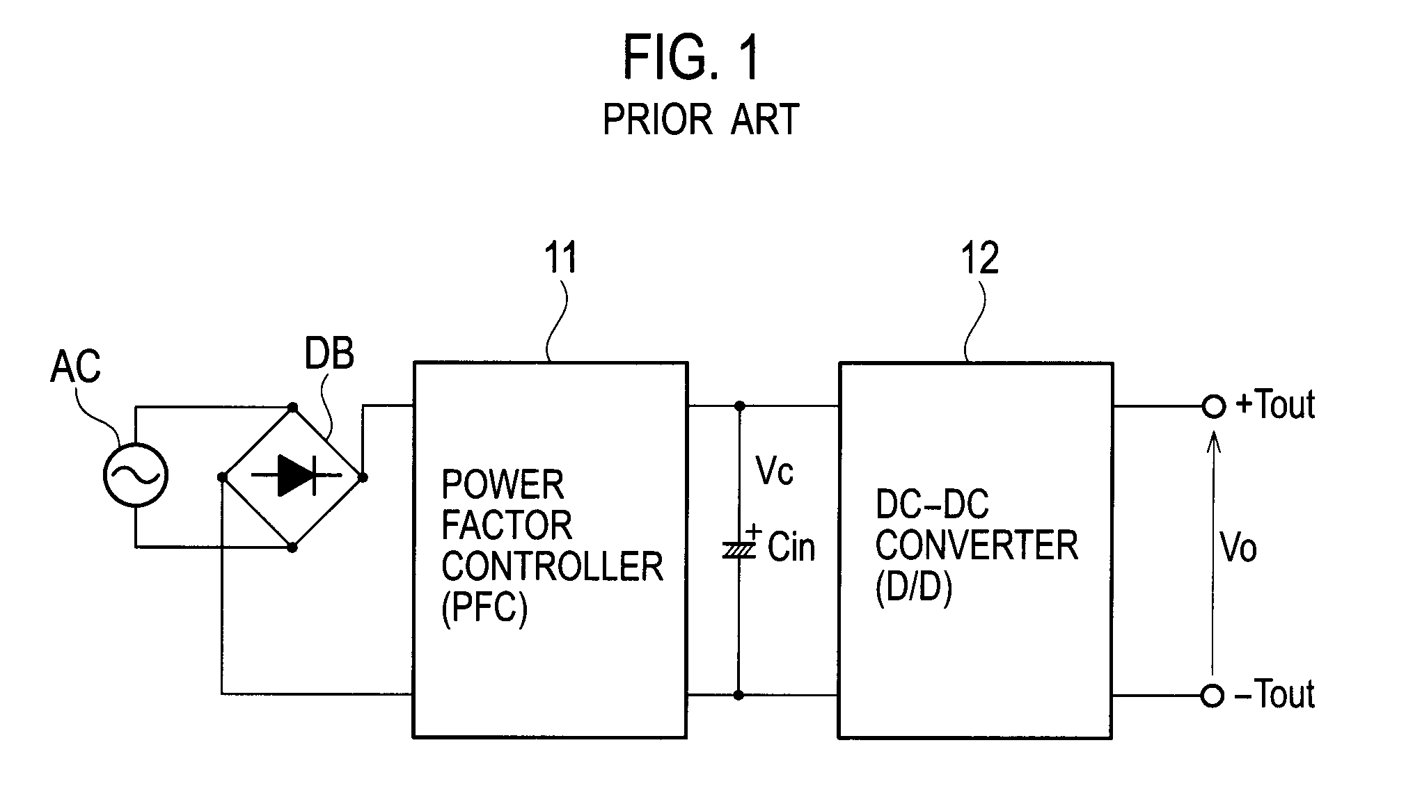
BACKGROUND OF THE INVENTION[0001]1. Field of the Invention[0002]The present invention relates to an AC-DC (alternate current-direct current) converter for converting alternating current to direct current. More particularly, the invention relates to a technique of reducing an input current in outputting a leak voltage.[0003]2. Description of the Related Art[0004]FIG. 1 shows a constitution of a conventional AC-DC converter disclosed in U.S. Pat. No. 5,960,207. The AC-DC converter includes a rectifier DB consisting of a diode bridge, an active power factor controller (PFC) 11, an input capacitor Cin and a DC-DC (direct current-direct current) converter (D / D) 12. The AC-DC converter operates as follows.[0005]In operation, the rectifier DB rectifies AC power (85˜265V) supplied from a commercial power source AC and outputs the full-wave rectified power to the power factor controller 11. If the power factor controller 11 is a type of global use, it boosts an output voltage of the rectifie...

Claims


Application Information

Patent Timeline
Patent Type & Authority Applications(United States)
IPC IPC(8): H02M7/68
CPCY02B70/126H02M1/4225Y02B70/10
Inventor USUI, HIROSHI
Owner SANKEN ELECTRIC CO LTD
Learn More