
Adjustable pedal system with ratio modifier

a ratio modifier and pedal system technology, applied in the direction of mechanical control devices, process and machine control, instruments, etc., can solve the problems of large package size, unfavorable driver adjustment method, and uncomfortable seat position for some drivers, and achieve constant ratio, high quality, cost-effective

Inactive Publication Date: 2009-01-29
DUS OPERATING INC
View PDF20 Cites 7 Cited by
  • Summary
  • Abstract
  • Description
  • Claims
  • Application Information

AI Technical Summary

Benefits of technology

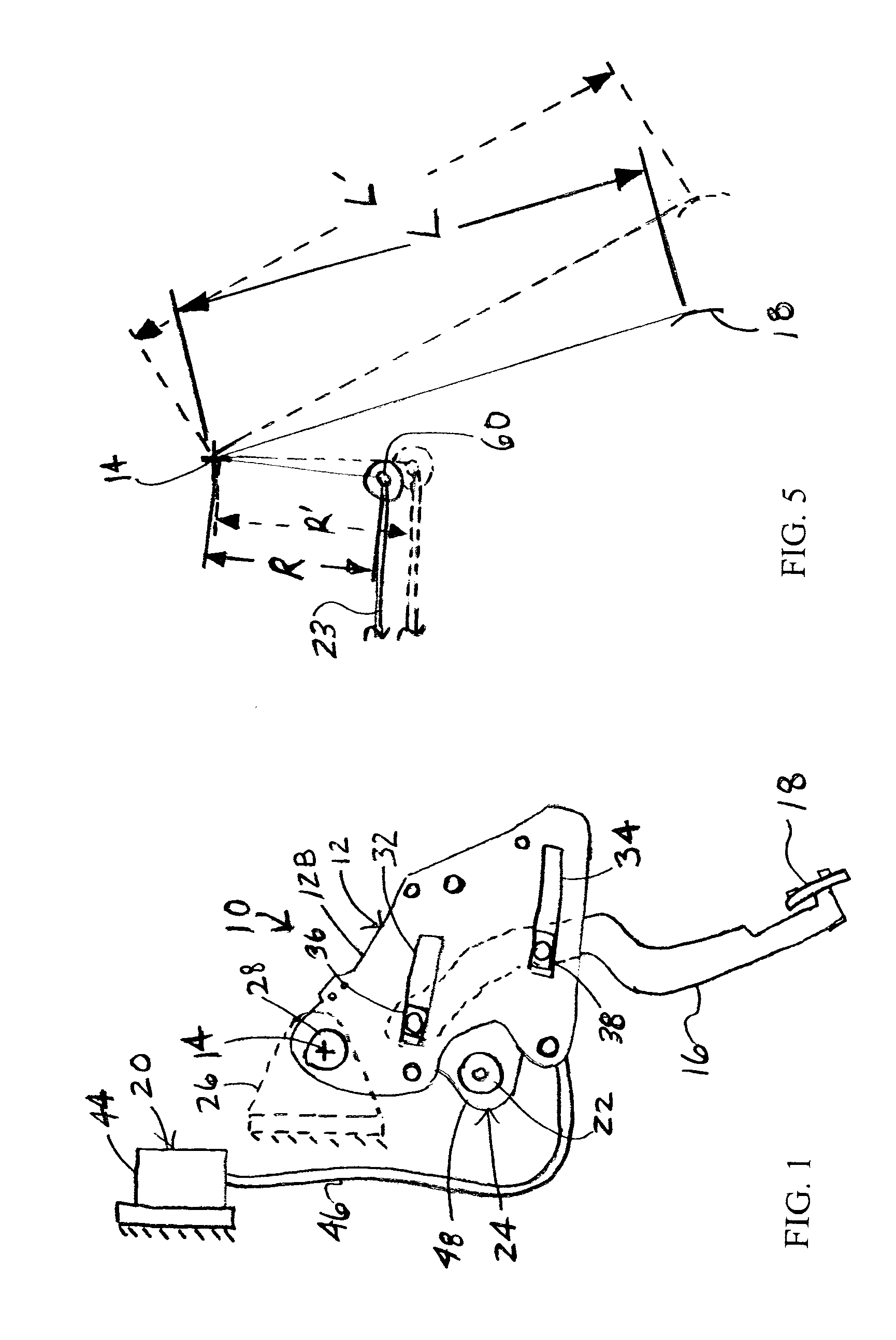
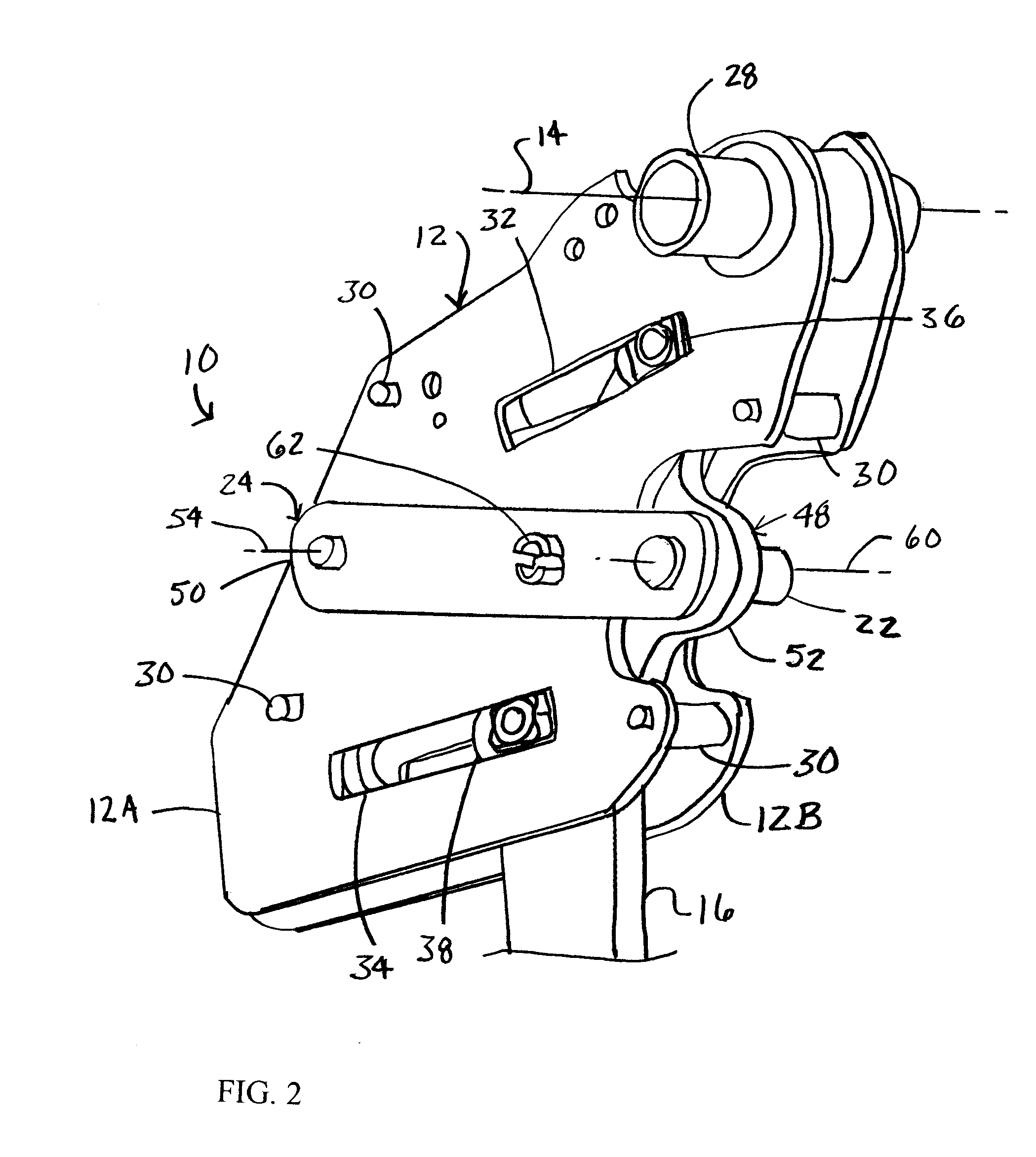
[0010]The present invention provides an adjustable pedal system which overcomes at least some of the above-noted problems of the related art. According to the present invention, an adjustable control pedal comprises, in combination, an upper arm pivotable about a stationary pivot axis and a lower arm carrying a pedal and operably connected to the upper arm so that the lower arm pivots the upper arm about the pivot axis when force is applied to the pedal. The lower arm is operatively connected to said upper arm for selected movement relative to the upper arm to adjust the position of the pedal between a forward position and a rearward position. A control pin is operably connected to the upper arm for rotation with the upper arm as the upper arm pivots about the pivot axis when force is applied to the pedal. An adjuster is operably connected to the control pin to adjust the position of the control pin relative to the pivot axis so that a ratio of a distance between the pivot axis and the pedal and a distance between the pivot axis and the control pin remains constant as the pedal is adjusted between the forward position and the rearward position.
[0011]According to another aspect of the present invention, an adjustable control pedal comprises, in combination, an upper arm pivotable about a stationary pivot axis and a lower arm carrying a pedal and operably connected to the upper arm so that the lower arm pivots the upper arm about the pivot axis when force is applied to the pedal. The lower arm is operatively connected to said upper arm for selected movement relative to said upper arm to adjust the position of the pedal between a forward position and a rearward position. A link is pivotally attached to the upper arm and a control pin is secured to the link for providing a control signal. Movement of the lower arm relative to the upper arm pivots the link to adjust the position of the control pin relative to the pivot axis so that a ratio of a distance between the pivot axis and the pedal and a distance between the pivot axis and the control pin remains constant as the pedal is adjusted between the forward position and the rearward position.
[0012]According to yet another aspect of the present invention, an adjustable control pedal comprises, in combination, an upper arm pivotable about a stationary pivot axis and a lower arm carrying a pedal and operably connected to the upper arm so that the lower arm pivots the upper arm about the pivot axis when force is applied to the pedal. The lower arm is operatively connected to the upper arm for selected movement relative to said upper arm to adjust the position of the pedal between a forward position and a rearward position. The upper arm includes first and second spaced-apart members each having first and second slots therein. Guides are operably secured to the lower arm that extend into the first and second slots of the upper arm respectively that move along the first and second slots of the upper arm as the lower arm is selectively moved relative to the upper arm. The lower arm extends between the first and second members with the guides extending between the first and second members, and the guides. A link is pivotally attached to the upper arm and a control pin secured to the link for providing a control signal. Movement of the lower arm relative to the upper arm pivots the link to adjust the position of the control pin relative to the pivot axis so that a ratio of a distance between the pivot axis and the pedal and a distance between the pivot axis and the control pin remains constant as the pedal is adjusted between the forward position and the rearward position. The link includes an inner link and an outer link rigidly secured together. The outer link is located outside the first and second members and is pivotably attached to the upper arm. The inner link extends between the first and second members and has first and second spaced-apart slots formed therein. The guides extend into the first and second slots of the inner link respectively, and the guides move along the first and second slots of the inner link as the lower arm is selectively moved relative to the upper arm to rotate the link relative to the upper arm.
[0013]From the foregoing disclosure and the following more detailed description of various preferred embodiments it will be apparent to those skilled in the art that the present invention provides a significant advance in the technology of adjustable pedal systems. Particularly significant in this regard is the potential the invention affords for providing a high quality, reliable, cost effective adjustable pedal system with a constant ratio. Additional features and advantages of various preferred embodiments will be better understood in view of the detailed description provided below.

Problems solved by technology

This adjustment method of moving the front seat along the tracks generally fills the need to accommodate drivers of various size, but it raises several concerns.
First, this adjustment method still may not accommodate all drivers due to very wide differences in anatomical dimensions of drivers.
Second, the position of the seat may be uncomfortable for some drivers as it nears the steering wheel.
While these adjustable pedal assemblies may maintain a constant ration, they each require a rather complex mechanism that is relatively expensive to produce and / or result in a relatively large package size.

Method used


Image

  • Adjustable pedal system with ratio modifier
  • Adjustable pedal system with ratio modifier
  • Adjustable pedal system with ratio modifier

Examples


Embodiment Construction

[0021]It will be apparent to those skilled in the art, that is, to those who have knowledge or experience in this area of technology, that many uses and design variations are possible for the improved adjustable control pedal disclosed herein. The following detailed discussion of various alternative and preferred embodiments will illustrate the general principles of the invention with reference to an adjustable brake pedal for use with a motor vehicle such as an automobile. Other embodiments suitable for other applications will be apparent to those skilled in the art given the benefit of this disclosure. For example, while the illustrated embodiments of the present invention are particularly adapted for use as a brake pedal, the adjustable control pedal can alternatively be adapted as a clutch, accelerator, or other desired control pedal within the scope of the present invention. Additionally, while the illustrated embodiments of the present invention are particularly adapted for us...


PUM


Abstract

An adjustable control pedal includes an upper arm and a lower arm carrying a pedal. The lower arm can be selectively moved relative to the upper arm to adjust the position of the pedal between a forward position and a rearward position. A control pin is operably connected to the upper arm for rotation with the upper arm to supply a control signal when force is applied to the pedal. An adjuster is operably connected to the control pin to adjust the position of the control pin relative to the pivot axis so that a ratio of a distance between the pivot axis and the pedal and a distance between the pivot axis and the control pin remains constant as the pedal is adjusted between the forward position and the rearward position.

Description

CROSS-REFERENCE TO RELATED APPLICATIONS[0001]Not ApplicableSTATEMENT REGARDING FEDERALLY SPONSORED RESEARCH[0002]Not ApplicableREFERENCE TO MICROFICHE APPENDIX[0003]Not ApplicableFIELD OF THE INVENTION[0004]The present invention generally relates to an improved control pedal for a motor vehicle and, more particularly, to a control pedal for a motor vehicle which is selectively adjustable to desired positions.BACKGROUND OF THE INVENTION[0005]Control pedals are typically provided in a motor vehicle, such as an automobile, which are foot operated by the driver. Separate control pedals are provided for operating brakes and an engine throttle. When the motor vehicle has a manual transmission, a third control pedal is provided for operating a transmission clutch. A front seat of the motor vehicle is typically mounted on tracks so that the seat is forwardly and rearwardly adjustable along the tracks to a plurality of positions so that the driver can adjust the front seat to the most advant...

Claims


Application Information

Patent Timeline
Patent Type & Authority Applications(United States)
IPC IPC(8): G05G1/14
CPCG05G1/405Y10T74/209Y10T74/206Y10T74/20528Y10T74/20888
Inventor BOOHER, JASON ALLENALLEN, JAMES ROBERTECKERLE, BRIAN JOHN
Owner DUS OPERATING INC
Learn More