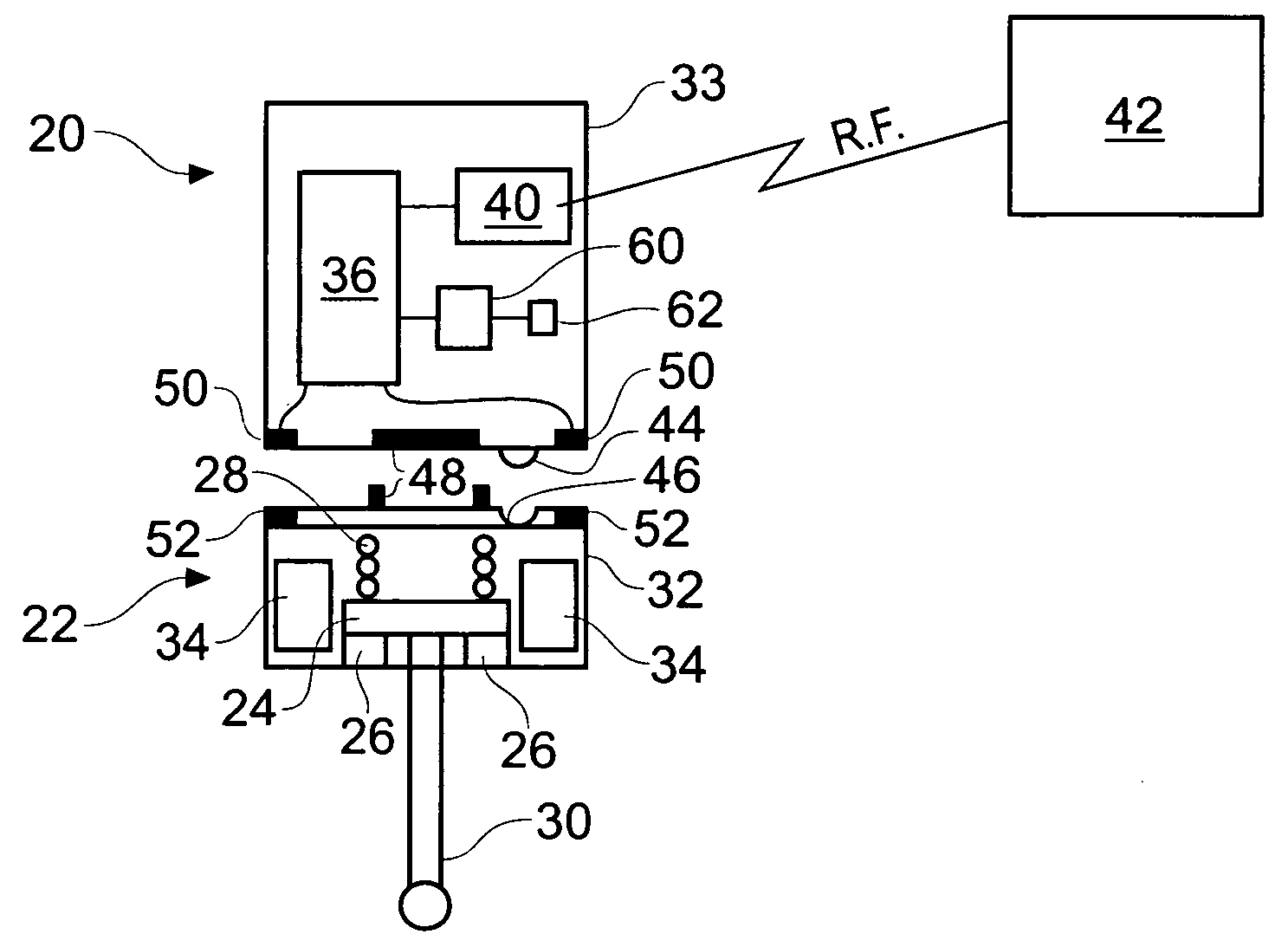
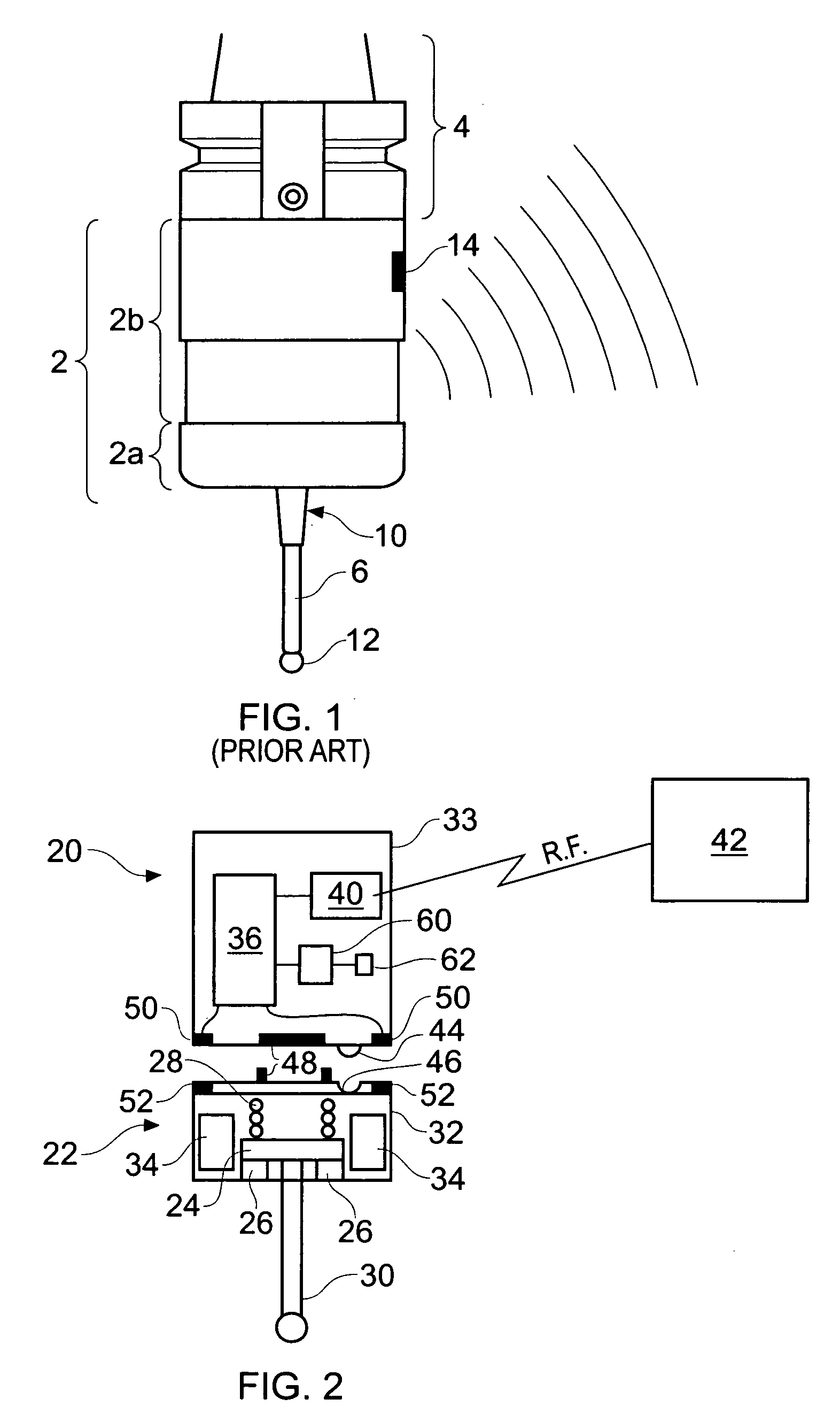
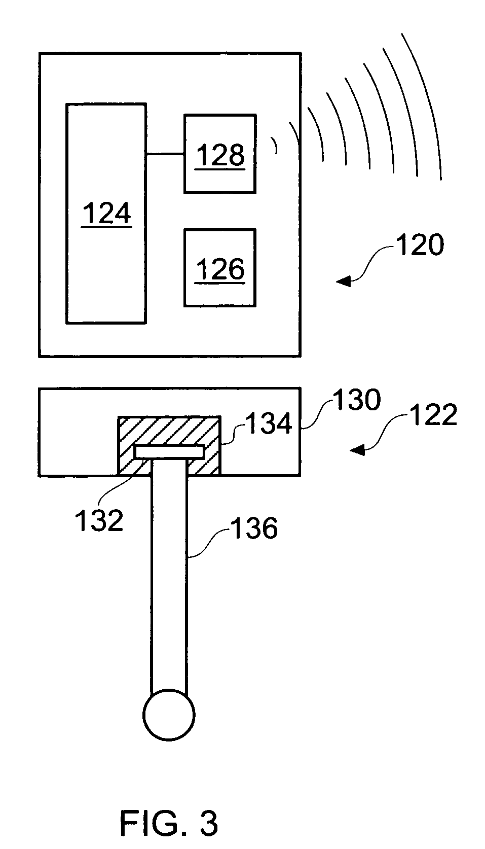
[0008]Providing a modular arrangement in accordance with the present invention has several benefits compared to prior art measurement probes of the type described above in which the majority of components are contained in a unitary probe housing. In particular, a modular measurement probe of the present invention allows most, or preferably all, of the
moving parts of the measurement probe to be incorporated into the stylus module. In this manner, it is the components of the stylus module that are subjected to
mechanical wear and tear during measurement probe operation. In contrast, the base module is arranged to contain parts of the measurement probe that are not subjected to any significant
mechanical wear and therefore has a much longer operational lifetime. For example, the base module may comprise a relatively complex communications portion, such as frequency hopping RF communications unit, in addition to the
processing electronics of the measurement portion that analyse raw stylus deflection signals in order to generate the required measurement data. The stylus module may contain some
electronics but preferably does not contain any of the relatively expensive
electronics that are necessary to implement the measurement probe. In this manner, the stylus module can be provided as a relatively low cost (e.g. disposable or consumable) module.
[0010]Providing such a failure mode allows the manufacturer to preset or control the expected lifetime of the stylus module. After failure of the stylus module, the measurement probe can be reactivated by
pairing a new stylus module with the base module. The present invention can thus provide a stylus module that is arranged to fail before the
moving parts therein become sufficiently worn that measurement accuracy is degraded. This ensures that measurement accuracy is maintained. Furthermore, the present invention can also allow a manufacturer to initially sell the modular measurement probe at a substantial discount relative to single piece measurement probes and to recoup the cost of providing such an initial discount through continuing sales of stylus modules. This also benefits users who may be unsure of the benefits of probing technology on their production process by allowing them to adopt the technology at a lower upfront cost.
[0012]Preferably, the at least one battery of the stylus module is permanently integrated within the stylus module. In other words, the one or more batteries of the stylus module may be provided or formed integrally with, and are preferably non-removable from, the stylus module. Advantageously, the at least one battery can not be removed from the housing of the stylus module without irreversible damaging at least part of the stylus module. For example, the stylus module may include a moulded plastic housing inside which the battery is contained. In such an example, removal of the battery may only be possible by physically breaking or
cutting open the plastic housing thereby reducing the strength of the stylus module and providing an opening through which
swarf,
coolant and other contaminants may enter. In this manner, the measurement probe can operate with a certain stylus module only until the batteries of that module are exhausted. At that point, the stylus module is disposed of and a replacement stylus module combined with the base module to provide an operable measurement probe. Providing such a dedicated battery can also allow the size of the stylus module to be reduced relative to a stylus module having a battery compartment for retaining standard size batteries. Conversely, bespoke batteries may be provided that maximise the amount of electrical power that can be stored in a stylus module of a certain size.
[0016]Providing a stylus module with an integrated stylus allows the stylus module to be appropriately calibrated prior to attachment to the base module. In other words, the in-situ measurement
probe calibration process that is typically required when a new stylus is attached to a measurement probe for the first time can be avoided by providing a stylus module with a stylus already secured thereto. For example, the
neutral position of the stylus relative to the housing may be appropriately centred or “jigged” during manufacture of the stylus module. If the stylus module also comprises a mechanical seating arrangement, the
spring force that is applied to return the stylus to the
neutral position may also be set as required during stylus module manufacture. In this manner, a broken stylus is replaced by attaching a new stylus module to the base module.
[0019]Advantageously, the stylus module comprises a deflection mechanism that mounts the stylus holder to the housing. Conveniently, the deflection mechanism urges the stylus holder into a repeatable neutral or zero position in the absence of any externally applied force. If a battery is provided as an integral part of the stylus module, the housing of the stylus module may be arranged such that any attempt to access the housing irreversibly damages the deflection mechanism. For example, the battery casing may form part of the structure that provides the deflection mechanism such that an attempt to remove a battery disturbs the deflection mechanism. In this manner, use of a stylus module after its battery has been exhausted can be prevented.
[0021]The measurement probe may comprise a so-called resistive touch trigger probe in which a trigger
signal is issued when a first locating element of the stylus holder becomes unseated from the associated second locating elements of the housing. Advantageously, the first and second locating elements form part of an
electrically conductive path such that, when a first locating element disengages a second locating element, the
electrically conductive path is broken. In such an arrangement, the measurement portion of the base module is conveniently arranged to monitor the resistance of the
electrically conductive path and to generate measurement data in the form of a trigger signal when the electrically conductive path is broken. The measurement portion may include
data processing electronics of known type, such as described in WO03 / 021182, to reduce the possibility of false triggers etc.


