
Polar modulation circuit, integrated circuit and radio apparatus

integrated circuit technology, applied in the direction of amplifiers, electrical devices, transmission, etc., can solve the problems of reducing the capacity of data stored in memory, reducing compensation accuracy, and difficult to provide high efficiency, so as to suppress the increase in the scale of a polar modulation circuit

Inactive Publication Date: 2009-01-22
PANASONIC CORP
View PDF6 Cites 27 Cited by
  • Summary
  • Abstract
  • Description
  • Claims
  • Application Information

AI Technical Summary

Benefits of technology

"The present invention relates to a polar modulation circuit with a distortion compensation circuit for compensating for distortion in an output signal from an amplifier in a radio apparatus. The invention aims to provide high efficiency in a power amplifier by using a linear modulation system. The invention uses a pre-distortion system that compensates for distortion in the output signal from the amplifier by using a memory to store the control voltage characteristics of the output signal amplitude and passing phase obtained during a saturation operation. The pre-distortion system includes an amplitude controller and an amplitude modulation unit to enhance the output response of the power amplifier. The invention improves the efficiency of the power amplifier in a polar modulation system and is useful in high-speed driving of a control voltage of a power amplifier."

Problems solved by technology

Thus, it has been difficult to provide high efficiency when related art quadrature modulation is applied to the linear modulation system.
In case the sampling interval of data stored in memory is broad, it is possible to reduce the capacity of data stored in memory with a tradeoff that the compensation accuracy is degraded.

Method used


Image

  • Polar modulation circuit, integrated circuit and radio apparatus
  • Polar modulation circuit, integrated circuit and radio apparatus
  • Polar modulation circuit, integrated circuit and radio apparatus

Examples


first embodiment

[0142]A first embodiment of the invention describes a polar modulation circuit including a distortion compensation circuit of the pre-distortion system capable of reducing the capacity of data stored in memory and suppressing an increase in the circuit scale related to distortion compensation in the polar modulation system while assuring the compensation accuracy, which advantages have been unavailable so far even through any combination of related art practices.

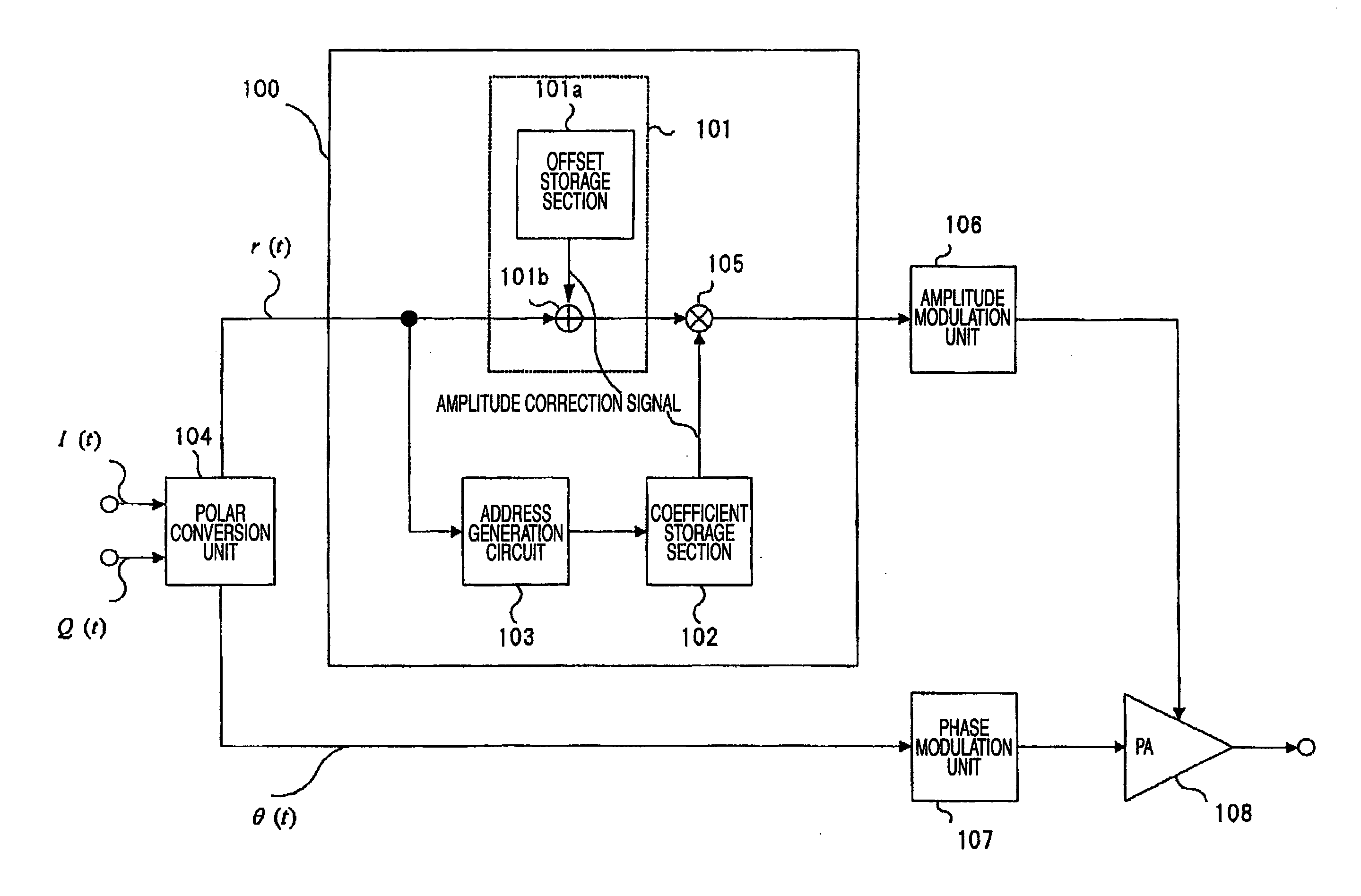
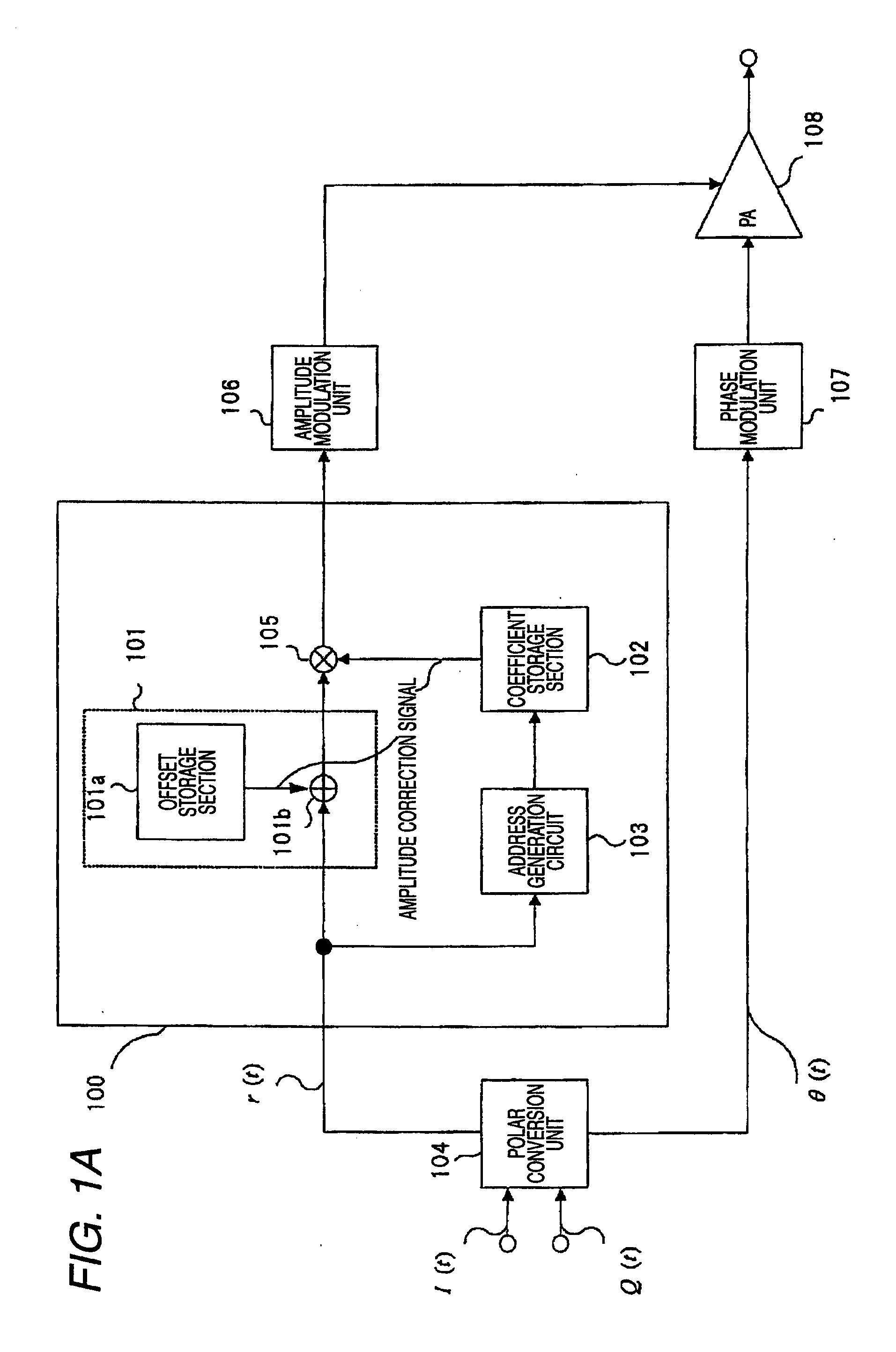
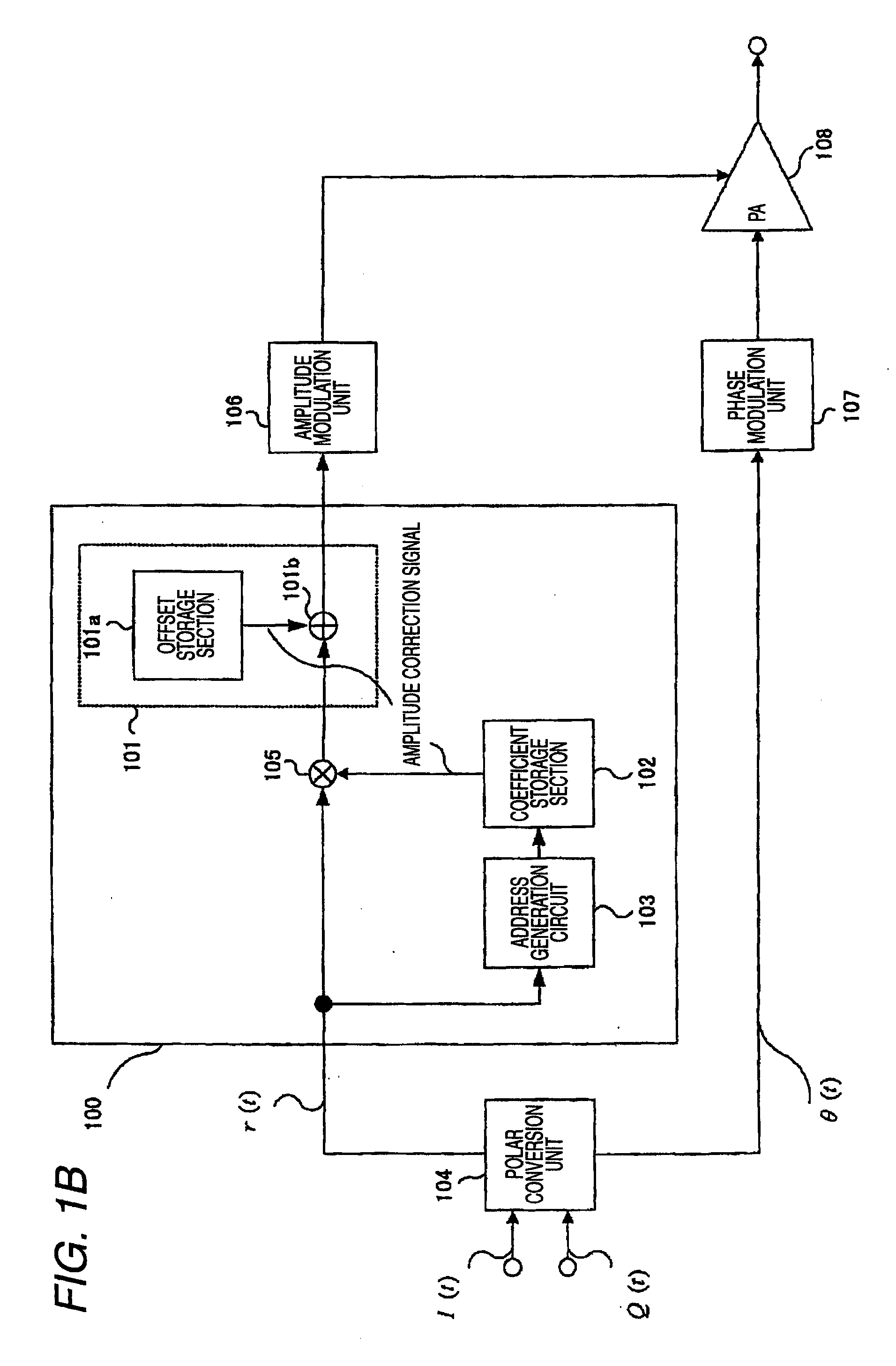
[0143]FIG. 1A shows a skeleton framework of a polar modulation circuit according to the first embodiment of the invention. As shown in FIG. 1A, a polar modulation circuit according to the first embodiment of the invention comprises polar conversion unit 104, an AM-AM characteristic compensation circuit 100, amplitude modulation unit 106, phase modulation unit 107, and a power amplifier 108.

[0144]The AM-AM characteristic compensation circuit 100 includes an offset compensation circuit 101, a coefficient storage section 102, a...

second embodiment

[0197]A second embodiment of the invention describes another example that is capable of compensating for the transient characteristic caused by the amplitude modulation by a power amplifier illustrated in FIG. 5A in accordance with the first embodiment of the invention.

[0198]FIG. 5B shows a skeleton framework of a polar modulation circuit according to the second embodiment of the invention. As shown in FIG. 5B, the polar modulation circuit according to the second embodiment of the invention comprises polar conversion unit 104, an AM-AM characteristic compensation circuit 2000, amplitude modulation unit 106, phase modulation unit 107, and a power amplifier 108.

[0199]The AM-AM characteristic compensation circuit 2000 includes an offset compensation circuit 101, a coefficient storage section 102, an address generation circuit 103, a transient characteristic compensation circuit 2001, and a multiplier circuit 105 and performs predetermined distortion compensation processing on amplitude...

third embodiment

[0207]A third embodiment of the invention describes a polar modulation circuit of which the circuit configuration is simplified in the polar modulation circuit shown in the second embodiment of the invention. FIG. 5D shows a skeleton framework of a polar modulation circuit according to the third embodiment of the invention. As shown in FIG. 5D, a polar modulation circuit according to the third embodiment of the invention comprises polar conversion unit 104, an AM-AM characteristic compensation circuit 2200, amplitude modulation unit 106, phase modulation unit 107, and a power amplifier 108.

[0208]The AM-AM characteristic compensation circuit 2200 includes an offset compensation circuit 101, a coefficient storage section 102, an address generation circuit 103, a multiplier circuit 105, and a multiplying DA converter (hereinafter referred to as an MDAC) 2201 and performs predetermined distortion compensation processing on amplitude information r(t). A same sign as in FIG. 5B or 5C of t...


PUM


Abstract

An object of the invention is to provide a polar modulation circuit capable of reducing the capacity of data stored in memory and suppressing an increase in the circuit scale related to distortion compensation while assuring the compensation accuracy. The polar modulation circuit according to the invention stores output signal characteristic relative to the control voltage at the steady state after input of the control voltage for a predetermined input amplitude of an input high frequency signal as the basis of distortion compensation of an amplifier separately into an offset storage section 101a which stores data used to add a predetermined DC offset voltage and a coefficient storage section 102 which stores data used for multiplication by a predetermined constant, thus reducing the circuit scale related to distortion compensation while assuring the compensation accuracy.

Description

TECHNICAL FIELD[0001]The present invention relates to a polar modulation circuit including a distortion compensation circuit for compensating for distortion of an output signal from an amplifier and an integrated circuit and radio apparatus including the polar modulation circuit.BACKGROUND ART[0002]In cell phone services in recent years, enhancement of communication speed is getting more critical with a growing demand for data communications on top of voice communications. For example, in the GSM (Global System for Mobile communications) system in widespread use mainly in the European and Asian regions, voice communications have conventionally employed GMSK modulation that shifts the phase of a carrier in accordance with transmit data. Further, The EDGE (Enhanced Data rates for GSM Evolution) system has been proposed whereby data communications are also performed with 3π / 8 rotating 8-PSK modulation (hereinafter referred to as 8-PSK modulation) including threefold bit information per...

Claims


Application Information

Patent Timeline
Patent Type & Authority Applications(United States)
IPC IPC(8): H04B1/04H04B1/62
CPCH03F1/3282H03F1/0222
Inventor SHIMIZU, YOSHITOSAITO, NORIAKI
Owner PANASONIC CORP
Learn More