
Light source apparatus and driving apparatus thereof

Active Publication Date: 2009-01-15
IND TECH RES INST
View PDF13 Cites 51 Cited by
  • Summary
  • Abstract
  • Description
  • Claims
  • Application Information

AI Technical Summary

Benefits of technology

[0008]Accordingly, a light source apparatus and a light source driving unit that effectively improves light uniformity and the driving efficiency of the light source module is disclosed.

Problems solved by technology

However, problems remain to be solved in the application of LEDs for backlighting of larger scale LCDs.
Such problems include limited light uniformity, low LED driving efficiency, and high cost LEDs.
Improved conversion efficiency and enhanced feedback control may also improve the LED light uniformity, but increases the complexity and price of the driving unit.
As a result, AC driving apparatus 100 may cause non-uniform light intensity in a backlight display.

Method used


Image

  • Light source apparatus and driving apparatus thereof
  • Light source apparatus and driving apparatus thereof
  • Light source apparatus and driving apparatus thereof

Examples


Embodiment Construction

[0033]In the following description, for purposes of explanation and not limitation, specific techniques and embodiments are set forth, such as particular sequences of steps, interfaces and configurations, in order to provide a thorough understanding of the techniques presented herein. While the techniques and embodiments will primarily be described in context with the accompanying drawings, those skilled in the art will further appreciate that the techniques and embodiments can also be practiced in other circuit types.

[0034]Reference will now be made in detail to the exemplary embodiments of the invention, examples of which are illustrated in the accompanying drawings. Wherever possible, the same reference numbers will be used throughout the drawings to refer to the same or like parts.

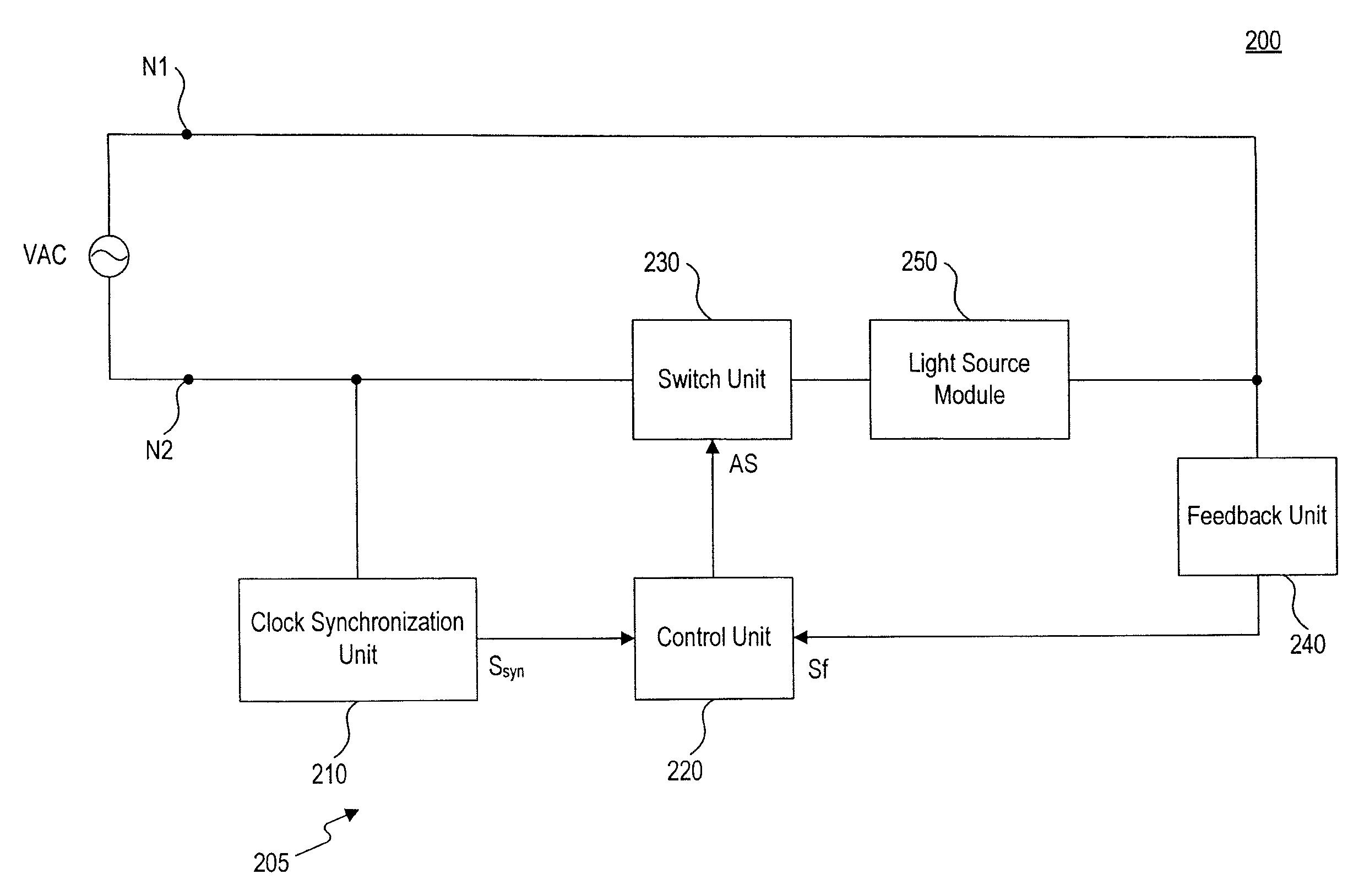
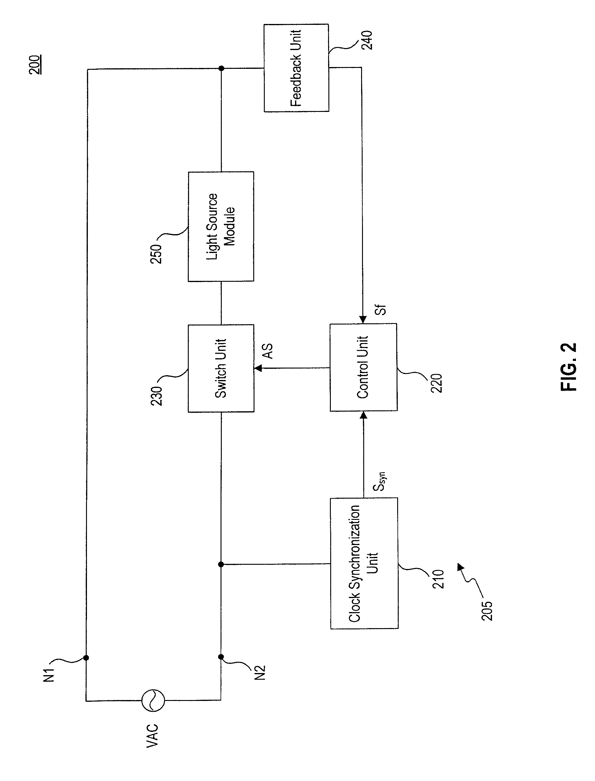
[0035]FIG. 2 is a block diagram of an embodiment of a light source apparatus 200 including a light source driving unit 205. Light source driving unit 205 includes a first node N1, a second node N2, a c...


PUM


Abstract

A light source driving apparatus to drive at least one light source module includes a switch unit for coupling in series with an AC power source and the light source module; a clock synchronization unit for coupling to the AC power source and to provide a clock synchronization signal in accordance with an AC voltage of the AC power source; a control unit coupled to receive the clock synchronization signal and to provide to the switch unit an adjusting signal according to a timing of the clock synchronization signal; and a feedback unit coupled to the control unit and to detect a load state of the light source module, the feedback unit configured to provide to the control unit a feedback signal having a value representative of the detected load state of the light source module. The control unit is configured to modulate a pulse width of the adjusting signal according to the feedback signal and a preset brightness value of the light source module, the switch unit responsive to the adjusting signal to open and close to apply the AC voltage to the light source module in accordance with the modulated pulse width.

Description

CROSS-REFERENCE TO RELATED APPLICATION [0001]This application is a continuation-in-part of parent U.S. application Ser. No. 11 / 830,857 filed Jul. 31, 2007 and claims priority of Taiwan application serial no. 96125235, filed Jul. 11, 2007. All disclosure of the parent U.S. and Taiwan applications is incorporated herein by reference.DESCRIPTION[0002]1. Technological Field[0003]Embodiments disclosed herein relate to a light source driving apparatus and methods for controlling a light source.[0004]2. Description of Related Art[0005]Light emitting diodes (LEDs) are commonly used as visual functionality indicators for electronic devices. LEDs are advantageous for use in electronic devices because LEDs consume little power and react quickly to input and changes in the state of a device. More recently, LEDs have been developed for backlighting liquid crystal displays (LCD), and for electronic illumination. LEDs are used in public electronic displays such as vehicle lamps, traffic lights, bu...

Claims


Application Information

Patent Timeline
IPC IPC(8): H05B41/16H01L33/00H05B37/02
CPCH05B33/0818H05B33/0827Y02B20/346H05B33/0869H05B33/0851H05B45/22H05B45/46H05B45/12Y02B20/30H05B45/10
Inventor HUANG, JUI-FENGCHUNG, LUNG-PIN
Owner IND TECH RES INST
Learn More