
Method and apparatus for burst error detection and digital communication device

Active Publication Date: 2009-01-01
MEDIATEK INC
View PDF17 Cites 7 Cited by
  • Summary
  • Abstract
  • Description
  • Claims
  • Application Information

AI Technical Summary

Problems solved by technology

Firstly, burst noise locations corresponding to the data stream are determined according to an error-check equation and accordingly generating a burst error indicator.

Method used


Image

  • Method and apparatus for burst error detection and digital communication device
  • Method and apparatus for burst error detection and digital communication device
  • Method and apparatus for burst error detection and digital communication device

Examples


Embodiment Construction

[0030]The following description is of the best-contemplated mode of carrying out the invention. This description is made for the purpose of illustrating the general principles of the invention and should not be taken in a limiting sense. The scope of the invention is best determined by reference to the appended claims.

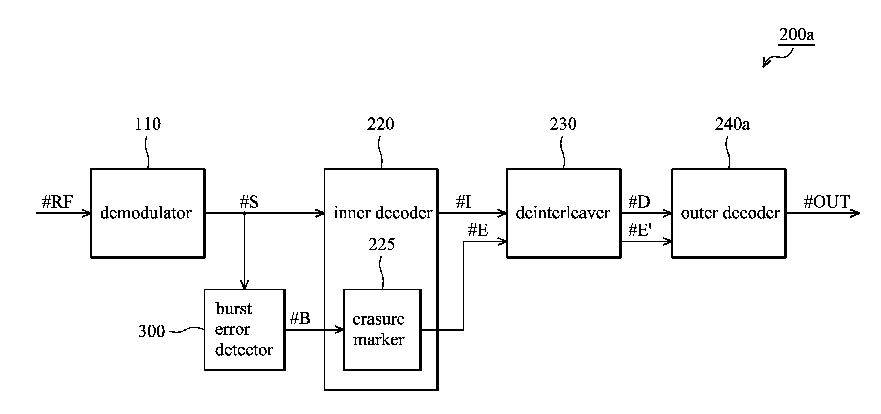
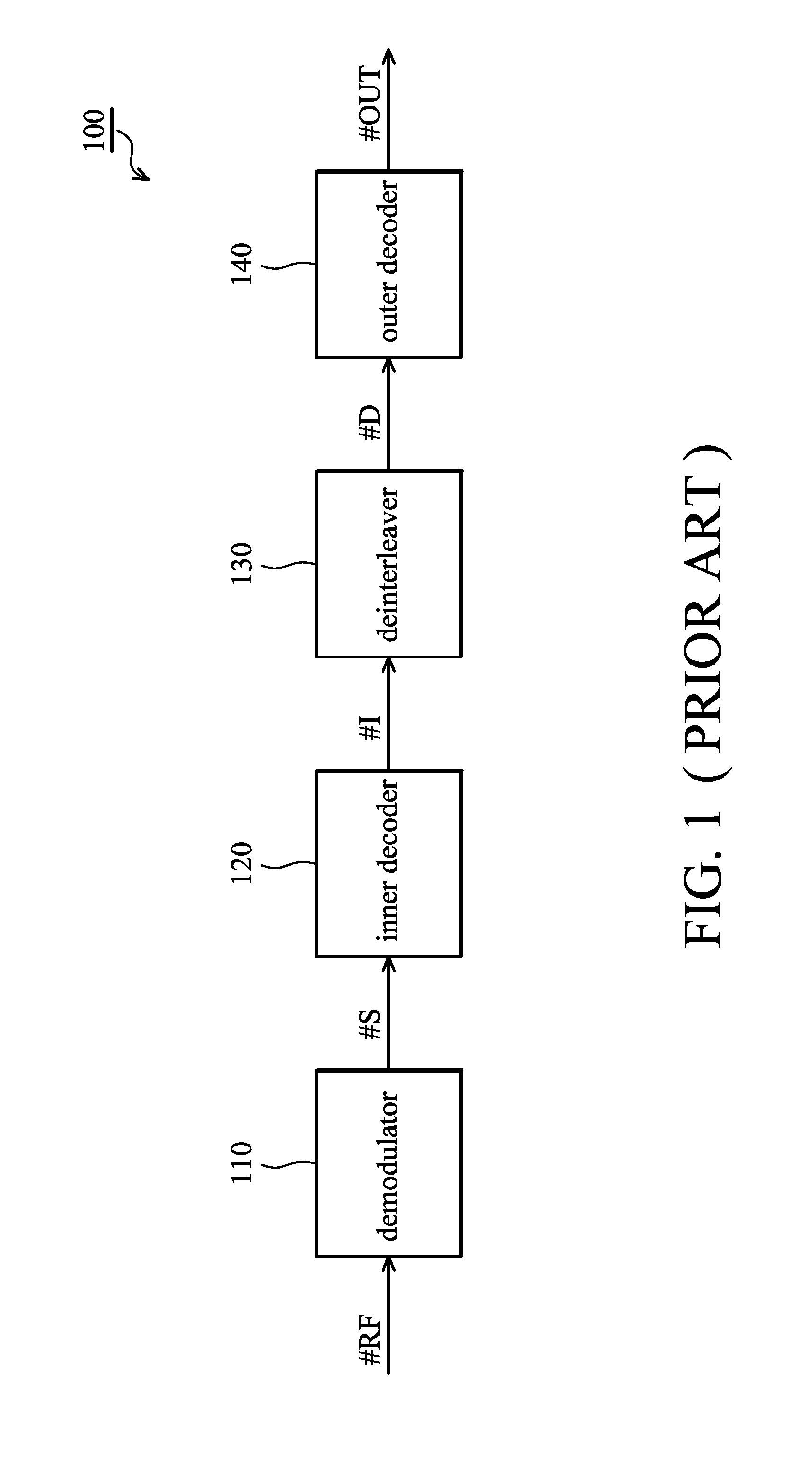
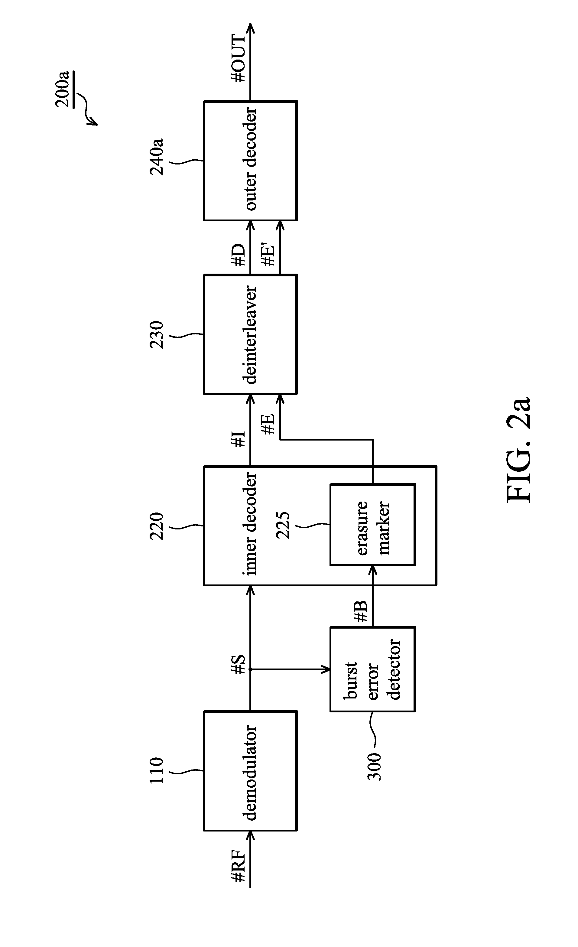
[0031]FIG. 2a shows an embodiment of a digital communication device 200a according to the invention. In the embodiment, a burst error detector 300 is provided to detect burst error based on the data stream #S output from the demodulator 110. The inner decoder 220 adapts an erasure marker 225 to output an erasure indicator #E based on burst error indicator #B output from the burst error detector 300. More specifically, the erasure marker 225 maps burst error indicator #B in a symbol level to corresponding bits while the inner decoder decodes the data stream #S into recovered bits. The deinterleaver 230 deinterleaves the erasure indicator #E to output a deinterleaved era...


PUM


Abstract

A digital communication device is provided for decoding a data stream to generate a receiver output. In the digital communication device, a burst error detector determines burst noise locations corresponding to the data stream according to an error-check equation and accordingly generates a burst error indicator. Thereafter, an inner decoder decodes the data stream to generate an inner decoded stream, comprising an erasure marker for performing an erasure marking process on the inner decoded stream based on the burst error indicator to generate an erasure indicator corresponding to the inner decoded stream. An outer decoder then decodes the inner decoded stream with reference to the erasure indicator to generate the receiver output.

Description

CROSS REFERENCE TO RELATED APPLICATIONS[0001]This application is a Continuation-In-Part of pending U.S. patent application Ser. No. 11 / 675,664, filed on 2007 Feb. 16 and entitled “apparatus AND METHOD for Determining A detected punctured position in punctured convolutional codes”, Ser. No. 11 / 684,029, filed 2007 Mar. 9 and entitled “apparatus AND METHOD for calculating error metrics in a digital communication system”, Ser. No. 11 / 160,927 filed on 2005 Jul. 15 and entitled “Error-correcting apparatus including multiple error-correcting modules functioning in parallel and related method”, and Ser. No. 11 / 161,014 filed on 2005 Jul. 19 and entitled “Apparatus selectively adopting different determining criteria in erasure marking procedure when performing decoding process, and method thereof”.BACKGROUND OF THE INVENTION[0002]1. Field of the Invention[0003]The invention relates to digital communication devices, and in particular, to an enhanced error-erasure decoding method applicable to ...

Claims


Application Information

Patent Timeline
IPC IPC(8): H03M13/17G06F11/07
CPCH03M13/2936H03M13/256
Inventor CHOU, RONG-LIANGLIOU, MING-LUEN
Owner MEDIATEK INC
Learn More