
Fuel Cell and Laminate

Inactive Publication Date: 2009-01-01
TOYOTA JIDOSHA KK
View PDF6 Cites 12 Cited by
  • Summary
  • Abstract
  • Description
  • Claims
  • Application Information

AI Technical Summary

Benefits of technology

[0005]It is an object of the present invention to prevent deterioration of sealability caused by deformation of seal members at supplying of reactant gases in a fuel cell stack.
[0006]A first aspect of the present invention relates to a fuel cell having a stack structure in which a plurality of laminates each including an anode and a cathode disposed on both sides of a electrolyte membrane are stacked on top of each other faith separators that sandwich the laminates. Each of the laminates has a seal member integrally formed on an outer periphery thereof for preventing leakage of reactant gases supplied onto a surface of the laminate, and a high-rigidity member having higher rigidity than the seal member surrounds at least a part of the seal member.
[0007]In the fuel cell, since the high-rigidity member can prevent deformation of the seal member, deterioration of sealability caused by deformation of the seal material at supplying of reactant gases can be prevented in a fuel cell stack.

Problems solved by technology

Such a defect is often observed when a material having a relatively low rigidity such as rubber is used for the seal members.

Method used


Image

  • Fuel Cell and Laminate
  • Fuel Cell and Laminate
  • Fuel Cell and Laminate

Examples


first embodiment

[0034]Description is hereinafter made of the present invention based on embodiments thereof in the following order.[0035]A.

[0036]A1. Configuration of fuel cell stack:

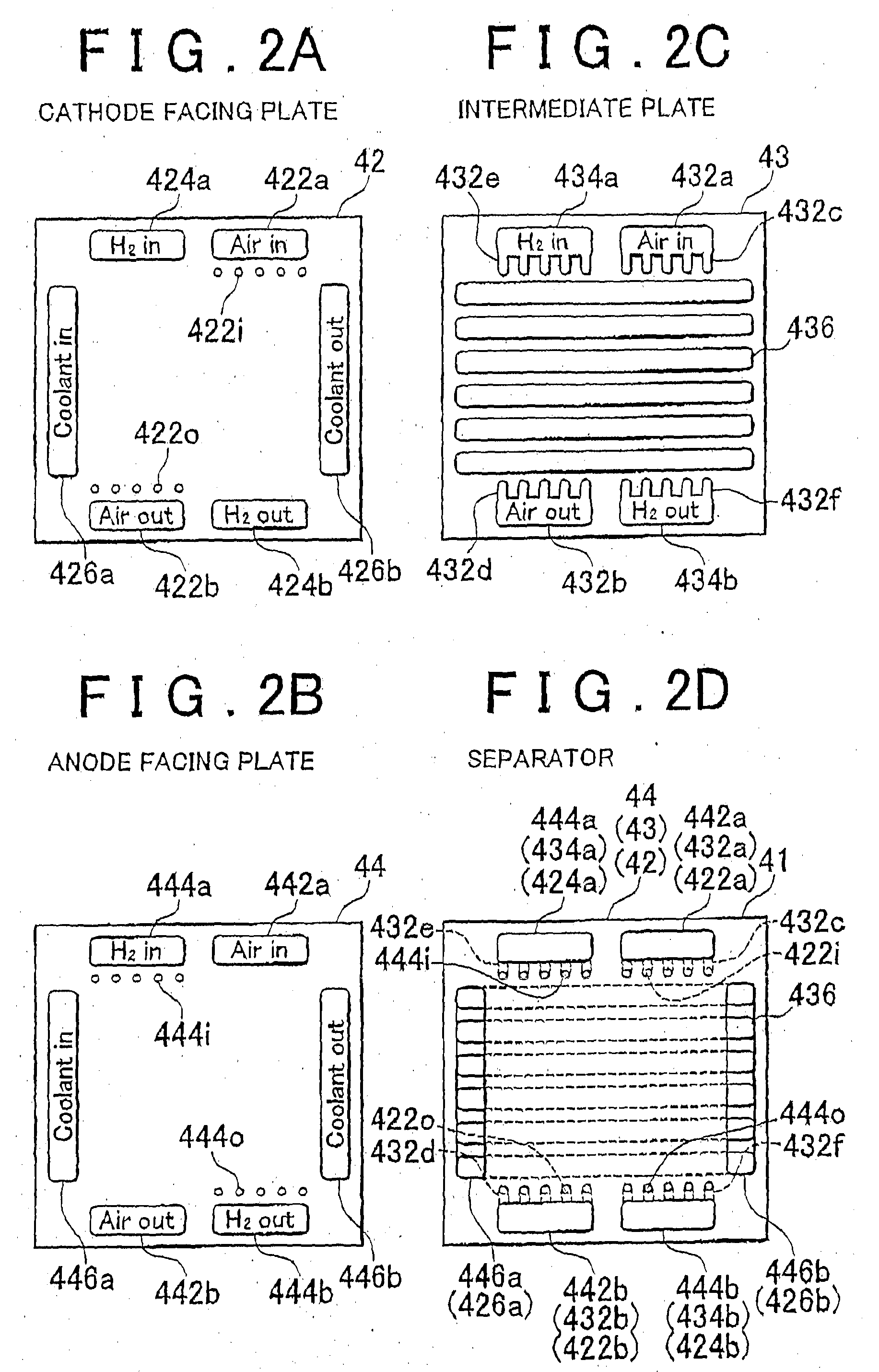
[0037]A2. Fuel cell module:[0038]A2.1. Separator:[0039]A2.2. Seal gasket-integrated MEA:

second embodiment

[0040]B.

[0041]C. Third Embodiment:

fourth embodiment

[0042]D.

[0043]E. Fifth Embodiment:

[0044]F. Modifications:

[0045]A. First Embodiment:

[0046]A1. Configuration of fuel cell stack:

[0047]FIG. 1 is a perspective view illustrating the general configuration of a fuel cell stack 100 as a first embodiment of the present invention. The fuel cell stack 100 has a stack structure in which a plurality of cells for generating electricity through an electrochemical reaction between hydrogen and oxygen are stacked on top of each other with separators interposed therebetween. Each cell has an anode, a cathode, and an electrolyte membrane having proton conductivity interposed therebetween as described later. In this embodiment, polymer membranes are used as the electrolyte membranes. ks the electrolyte other electrolytes such as a solid oxide may be used. The number of the cells can be arbitrary set based on the output power demanded to the fuel cell stack 100.

[0048]In the fuel cell stack 100, an end plate 10, an insulating plate 20, a current collect...


PUM

PropertyMeasurementUnit
Elasticityaaaaaaaaaa
Stiffnessaaaaaaaaaa
Deformation enthalpyaaaaaaaaaa

Abstract

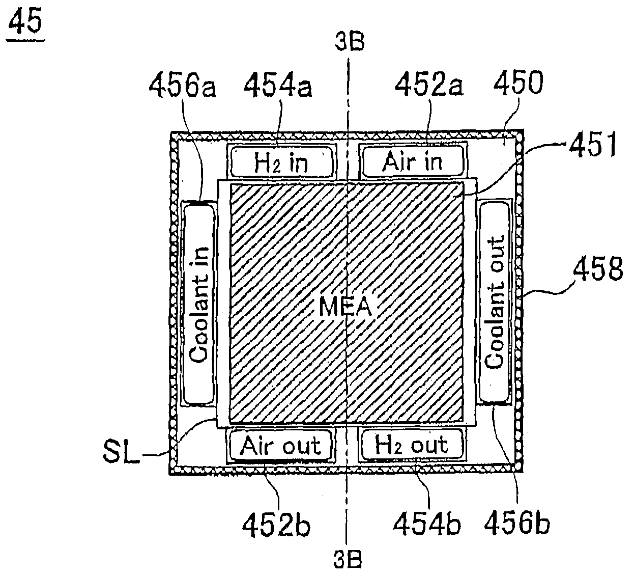
In a seal gasket-integrated MEA (45) in which a frame (450) having a sealing part (459) is integrally formed around a membrane-electrode assembly (MEA section 451), a high-rigidity member (458) having higher rigidity than the frame (450) is provide around a frame (450) having relatively low rigidity.

Description

FIELD OF THE INVENTION[0001]The present invention relates to a fuel cell and a laminate, and more particularly, to a laminate having an anode and a cathode on both sides of a electrolyte membrane, and a fuel cell having a stack structure in which a plurality of the laminates are stacked on top of each other with separators that sandwich the laminates.BACKGROUND OF THE INVENTION[0002]Fuel cells, which generate electricity through an electrochemical reaction between hydrogen and oxygen, are attracting attention as energy sources. A fuel cell has a stack structure in which membrane-electrode assemblies each having an anode (hydrogen electrode) and a cathode (oxygen electrode) on both sides of a electrolyte membrane and separators are stacked alternately (the fuel cell having such a stack structure is hereinafter referred to also as “fuel cell stack”).[0003]As for such fuel cell stacks, various techniques to prevent leakage of reactant gases (fuel gas and oxidant gas) have been proposed...

Claims


Application Information

Patent Timeline
IPC IPC(8): H01M2/08
CPCH01M8/0273H01M8/0276Y02E60/50H01M8/241H01M2008/1095H01M8/0284H01M8/0271H01M8/0267H01M8/2457H01M8/2483
Inventor SHIZUKU, FUMISHIGESANO, SEIJIKAJIWARA, TAKASHISATO, HIROMICHIHOTTA, YUTAKAOHTA, YOSHIFUMI
Owner TOYOTA JIDOSHA KK
Learn More