
Lens barrel and imaging device

Active Publication Date: 2009-01-01
PANASONIC CORP
View PDF4 Cites 14 Cited by
  • Summary
  • Abstract
  • Description
  • Claims
  • Application Information

AI Technical Summary

Benefits of technology

[0011]According to the present invention, even if any impact is applied to the lens barrel, for example, due to a fall with the barrel being extended, the first contact portion provided on the rotational barrel and the second contact portion provided on the fixed member are brought into contact with each other to lock rotation of the rotational barrel. More specifically, the engagement between the first contact portion and the second contact portion, or a frictional force generated therebetween, reliably inhibits the rotational barrel from rotating about its axial center, thereby making it possible to prevent gears from being damaged, for example.

Problems solved by technology

Where only the rotational barrel is rotated with the motor for rotating the rotational barrel being stopped, load is applied to a mechanism used for extension, including gear trains, for example, so that in some cases, gears might be damaged.
However, in the case of the structure as described in Japanese Laid-Open Patent Publication No. 2003-279827, the effect of inhibiting the rotation of the rotational barrel is limited, and there are large gaps between the cam grooves and the cam pins, resulting in a problem where image blur might occur.

Method used


Image

  • Lens barrel and imaging device
  • Lens barrel and imaging device
  • Lens barrel and imaging device

Examples


first embodiment

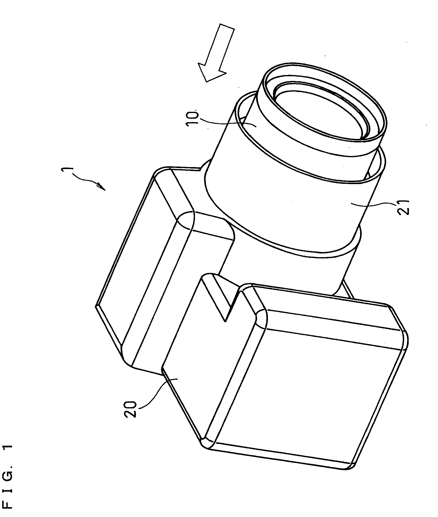
[0026]FIG. 1 illustrates the external appearance of a digital still camera (hereinafter, simply referred to as a “camera”) 1 including a lens barrel according to a first embodiment of the present invention. The camera 1 includes a camera body 20, and a collapsible lens barrel 10, which is retractable into and extendable from the camera body 20. The camera body 20 includes a barrel storage portion 21 for protecting the lens barrel 10, so that the lens barrel 10 can entirely retract into the barrel storage portion 21.

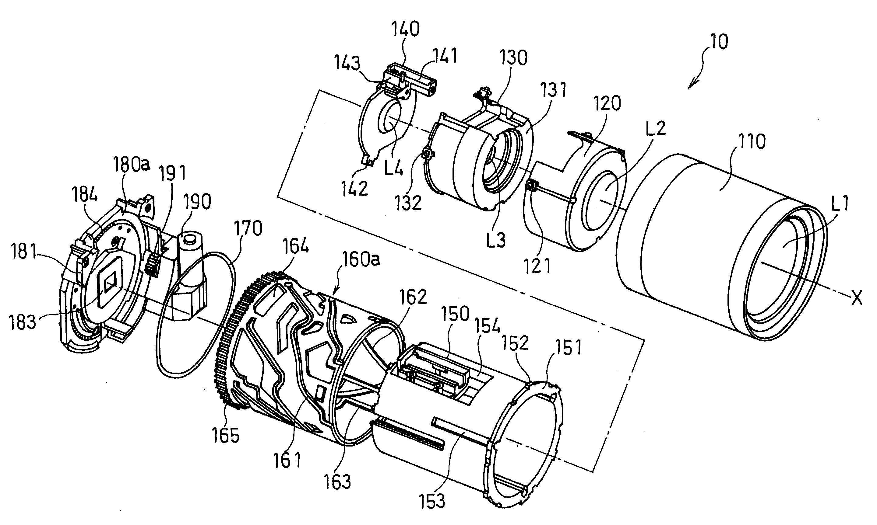
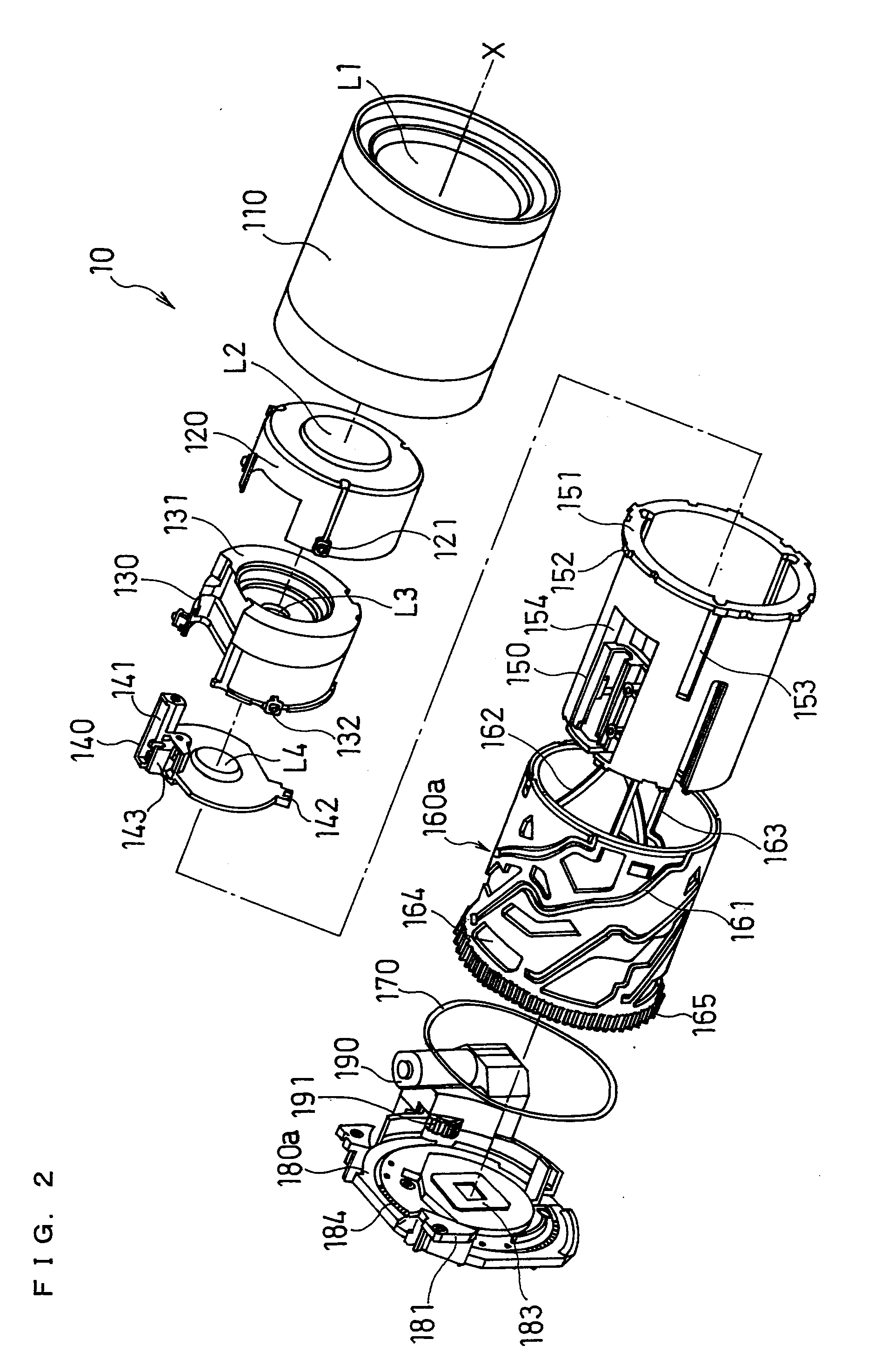
[0027]FIG. 2 is an exploded perspective view of the lens barrel 10. The lens barrel 10 includes a first-group lens unit 110, a second-group lens unit 120, a third-group lens unit 130, a fourth-group lens unit 140, a fixed barrel 150, a rotational barrel 160a, a wave spring 170, a fixed member 180a, and a motor unit 190.

[0028]Before concretely describing the configuration of the lens barrel 10, the optical imaging system of the lens barrel 10 will be briefly described in t...

second embodiment

[0069]FIG. 12 illustrates the configuration of a rotational barrel of a lens barrel according to a second embodiment of the present invention. FIG. 13 illustrates the configuration of a fixed member according to the second embodiment of the present invention. In the present embodiment, the lens barrel includes a rotational barrel 160b and a fixed member 180b, in place of the rotational barrel 160a and the fixed member 180a, respectively, in the first embodiment. Note that other elements are the same as those of the lens barrel in the first embodiment.

[0070]In the lens barrel according to the first embodiment, the first engagement portion 166 provided at the end of the rotational barrel 160a engages with the second engagement portions 184 provided on the fixed member 180a, thereby inhibiting rotation of the rotational barrel 160a when any impact is applied to the lens barrel. On the other hand, the lens barrel according to the present embodiment has a frictional portion 167 provided ...


PUM


Abstract

A collapsible lens barrel is provided, including a mechanism capable of reliably inhibiting rotation of a rotational barrel even if any impact is applied thereto, for example, due to a fall with the barrel being extended. When the rotational barrel is pressed upon a fixed member due to impact in defiance of the biasing force of a wave spring, a first engagement portion provided at a camera body-side end of the rotational barrel engages with second engagement portions provided on a subject-side surface of the fixed member, which locks rotation of the rotational barrel, thereby making it possible to prevent gears from being damaged, for example.

Description

FIELD OF THE INVENTION[0001]The present invention relates to collapsible lens barrels, and imaging devices having such a lens barrel mounted thereon. The present invention particularly relates to a lens barrel including a mechanism for preventing damage due to drop impact, for example.BACKGROUND OF THE INVENTION[0002]Widespread use of the digital still camera and the video movie camera that use the solid-state image sensor results in a strong demand for smaller imaging devices. In order to satisfy such a demand for smaller imaging devices and to further improve portability, the so-called “collapsible lens barrel”, which retracts into a camera body when performing no image shooting, has been widely used. The length of the collapsible lens barrel is changed by a motor rotating a rotational barrel to move an optical imaging system in the optical axis direction.[0003]As for conventional collapsible lens barrels, if any impact is applied thereto, for example, due to a fall with the barre...

Claims


Application Information

Patent Timeline
IPC IPC(8): G02B7/04
CPCG02B27/646G02B7/102
Inventor NAKADA, TOSHIYUKIKAWANE, HIDEAKIFUJINAKA, HIROYASUENGUCHI, ITARU
Owner PANASONIC CORP
Learn More