
Method, apparatus and a computer program product for utilizing a graphical processing unit to provide depth information for autostereoscopic display

a technology of depth information and graphical processing unit, which is applied in the field of mobile electronic device technology, can solve the problems of consuming resources, affecting the display effect, and affecting the display effect, and achieves the effect of reducing the processing load of the application processor

Inactive Publication Date: 2009-01-01
NOKIA CORP
View PDF7 Cites 47 Cited by
  • Summary
  • Abstract
  • Description
  • Claims
  • Application Information

AI Technical Summary

Benefits of technology

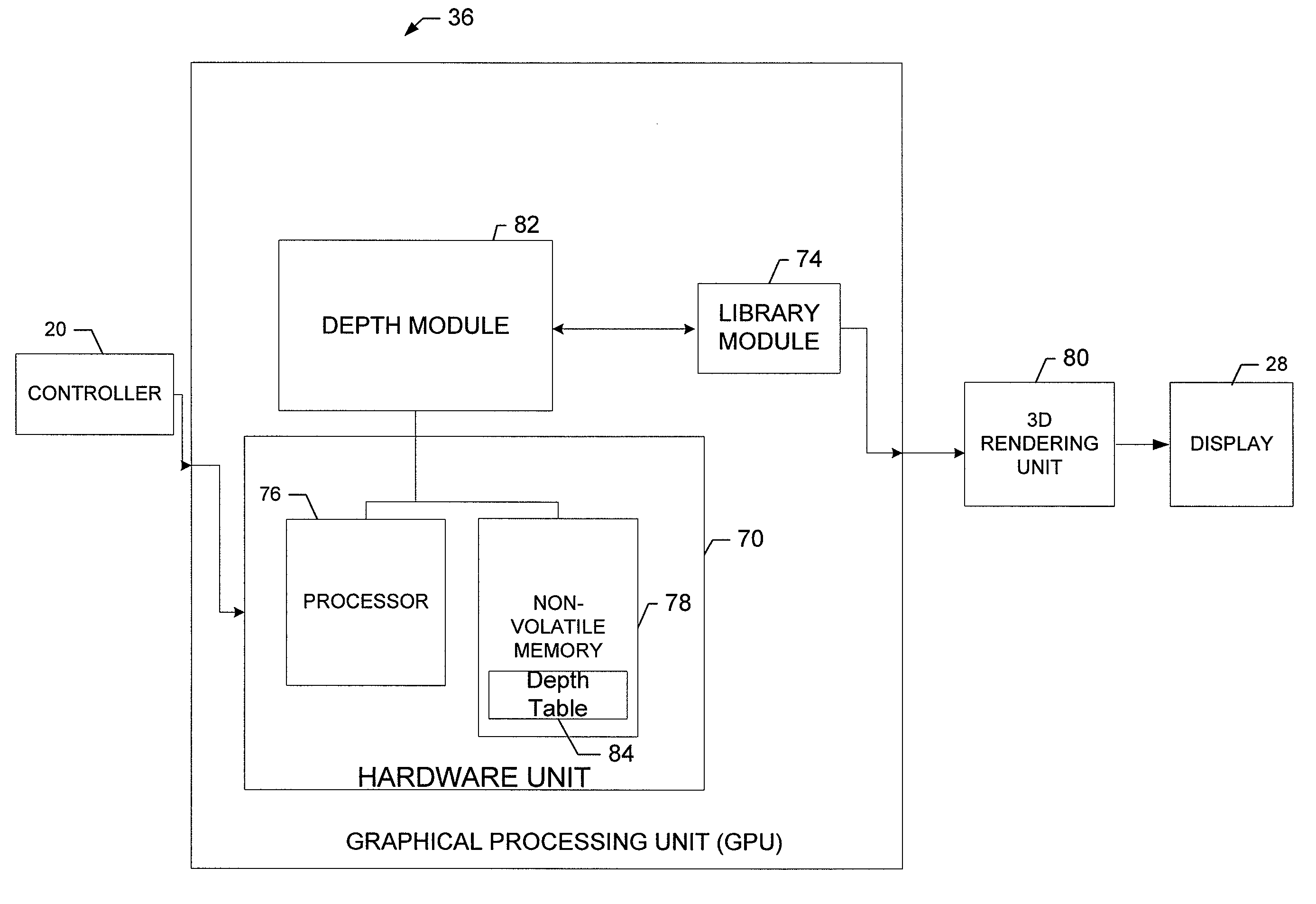
[0007]The exemplary embodiments of the present invention provide a method, computer program product and device for processing of graphics content in electronic devices such as mobile terminals (e.g., mobile phone) in real-time to be suitable for 3D rendering to multi-view autostereoscopic 3D displays. In the exemplary embodiments of the present invention, depth information of the original 2D graphics image is processed and presented as a 2D graphics image. As such, depth information (i.e., Z-map) associated with the 2D graphics image is created using the graphics functions of the GPU and thus the application processor is not needed for processing the depth information. In this regard, the processing load of the application processor is decreased freeing the application processor to perform or execute other functions.

Problems solved by technology

Since graphics rendering is a highly computationally intensive task, in modern computing devices an enormous amount of computations are often performed in a special hardware unit called a Graphics Processing Unit (GPU).
Calculating the depth information into numeric data and processing this data consumes resources and may slow down the 3D rendering process.

Method used


Image

  • Method, apparatus and a computer program product for utilizing a graphical processing unit to provide depth information for autostereoscopic display
  • Method, apparatus and a computer program product for utilizing a graphical processing unit to provide depth information for autostereoscopic display
  • Method, apparatus and a computer program product for utilizing a graphical processing unit to provide depth information for autostereoscopic display

Examples


Embodiment Construction

[0017]The present invention now will be described more fully hereinafter with reference to the accompanying drawings, in which some, but not all embodiments of the inventions are shown. Indeed, these inventions may be embodied in many different forms and should not be construed as limited to the embodiments set forth herein; rather, these embodiments are provided so that this disclosure will satisfy applicable legal requirements. Like numbers refer to like elements throughout.

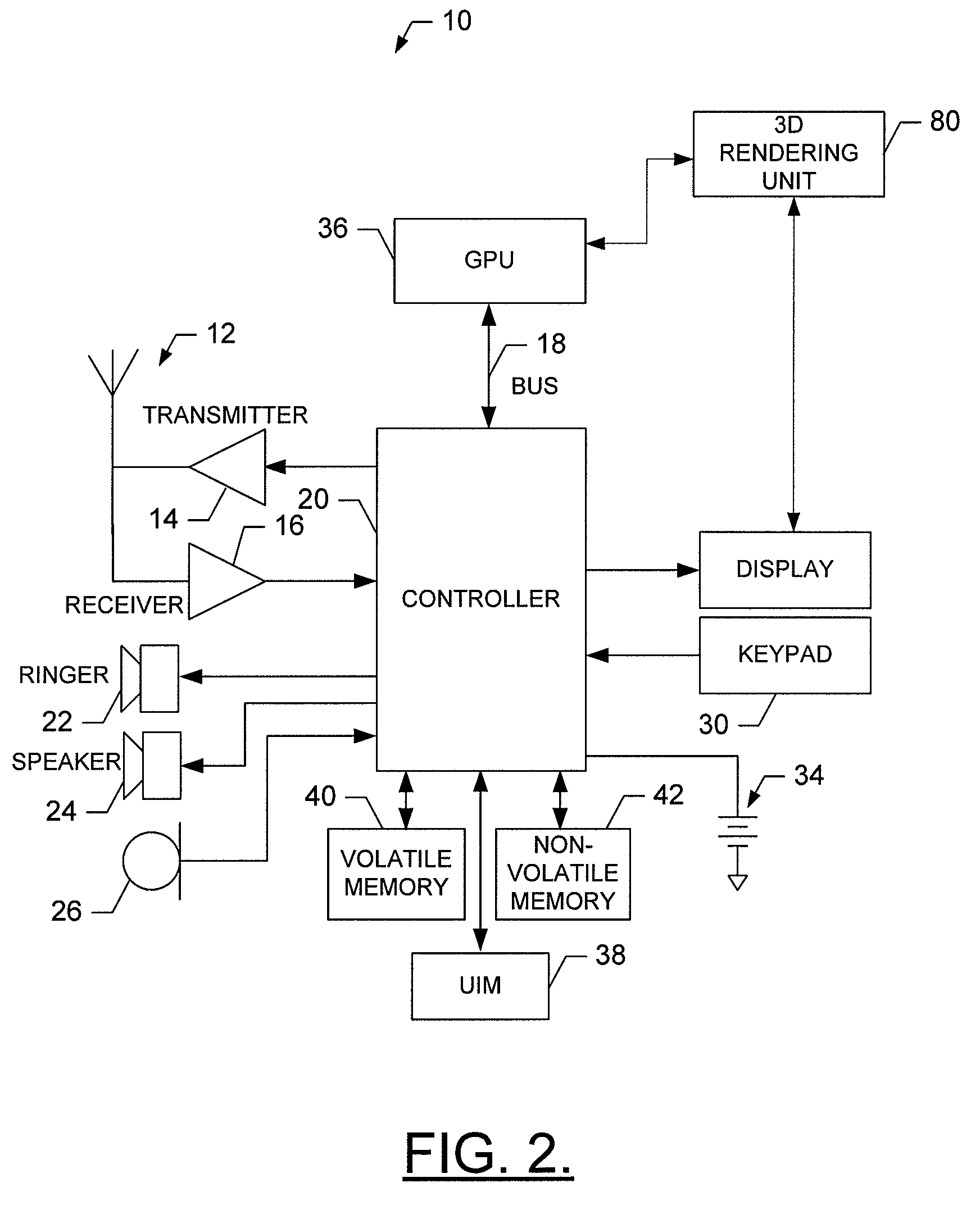
[0018]Referring now to FIG. 2, an illustration of a block diagram of a mobile terminal 10 that would benefit from embodiments of the present invention is provided. It should be understood, however, that a mobile telephone as illustrated and hereinafter described is merely illustrative of one type of mobile terminal that would benefit from embodiments of the present invention and, therefore, should not be taken to limit the scope of the present invention. While several embodiments of the mobile terminal 10 are i...


PUM


Abstract

A device for generating a 3D image based on 2D graphical content of an image and depth information (i.e., Z-map) to be displayed on a display includes an application processor, a graphical processing unit (GPU), a 3D rendering unit and a display. The application processor is capable of sending 2D graphical content to the GPU, which is stored in memory. The GPU also includes a depth table having predefined depth information corresponding to the 2D graphical content. The GPU includes a depth module which monitors or identifies the 2D graphical content and requests a graphics library to paint a corresponding area in the Z-map that has the same size and position in the Z-map as that of the 2D graphical content. The GPU sends the 2D graphical content and the painted Z-map to a 3D rendering unit which creates a 3D image to be shown on a display.

Description

TECHNOLOGICAL FIELD[0001]Embodiments of the present invention relate generally to mobile electronic device technology and, more particularly relate to methods, apparatuses, and a computer program product for processing of graphics content to facilitate display of three-dimensional content on autostereoscopic displays.BACKGROUND[0002]The modern communications era has brought about a tremendous expansion of wireline and wireless networks. Computer networks, television networks, and telephony networks are experiencing an unprecedented technological expansion fueled by consumer demand. Wireless and mobile networking technologies have addressed related consumer demands while providing more flexibility and immediacy of information transfer.[0003]Current and future networking technologies continue to facilitate ease of information transfer and convenience to users. One area in which there is a demand to increase ease of information transfer and convenience to users relates to provision of ...

Claims


Application Information

Patent Timeline
Patent Type & Authority Applications(United States)
IPC IPC(8): G06T15/40
CPCG06T15/005H04N2213/003H04N13/0275H04N13/0022H04N13/275H04N13/128
Inventor VITIKAINEN, TIMOSUOKNUUTI, MARKORUUTU, JUSSIKORHONEN, OSSI
Owner NOKIA CORP
Learn More