Antenna Branching Filter

Inactive Publication Date: 2009-01-01
NIHON DEMPA KOGYO CO LTD
View PDF5 Cites 23 Cited by
  • Summary
  • Abstract
  • Description
  • Claims
  • Application Information

AI Technical Summary

Benefits of technology

[0012]The object of the present invention is to provide an antenna duplexer which ensures the phase matching function of a phase shifter, and can improve the attenuation characteristic in a frequency band out of pass band of the high band side filter and the low band side filter.
[0027]As described above, since the present invention (the embodiments correspond to FIG. 1, FIG. 5 and FIG. 11) provides an inductor or a capacitor composing a phase shifter, and an LC resonating resonance capacitor or an LC resonating inductor so as to obtain a attenuation characteristic in an optional band in an out-of-pass band of the filters by the LC resonance, it has the effect of ensuring the phase matching function of the phase shifter and improving the attenuation characteristics in an optional frequency band in an out-of-pass band of the high band side and the low band side filters. In addition, according to other inventions (the embodiments correspond to FIG. 7 and FIG. 9), by series resonation in a signal path in the phase-shifter, or by parallel resonation between the signal path and the ground, the band-pass function is obtained to the pass-band of the filter so that the amount of attenuation in an out-of-frequency band corresponding to the band-pass can be finally improved.

Problems solved by technology

However, as shown in FIG. 14A and FIG. 14B which partially enlarges FIG. 14A, there is a problem such that in the conventional frequency characteristics, the required out-of-band attenuation characteristics can not be ensured, for instance, when the center frequency in a pass band of the low band side filter is supposed to be fL, the attenuation amount in the vicinity of twice frequency (2×fL) of this center frequency cannot be guaranteed.
In particular, the spuriousness of higher harmonics corresponding to the frequency twice as many as that of the pass band is high.
However, if the amount of attenuation in the vicinity of 2×fL is small, it becomes a noise signal in other frequency bands allocated to, for instance, a portable terminal.

Method used


Image

  • Antenna Branching Filter
  • Antenna Branching Filter
  • Antenna Branching Filter

Examples


modified example

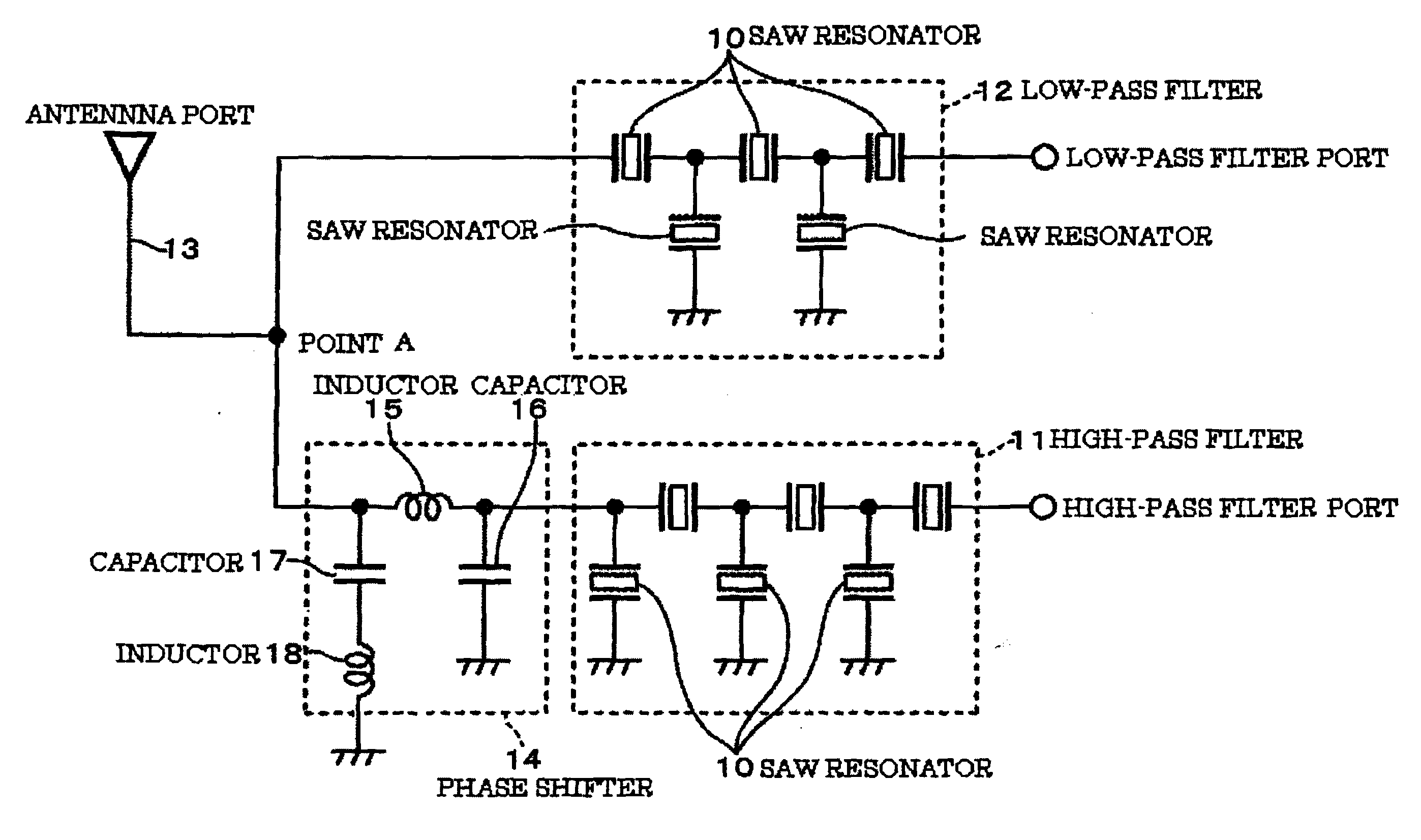
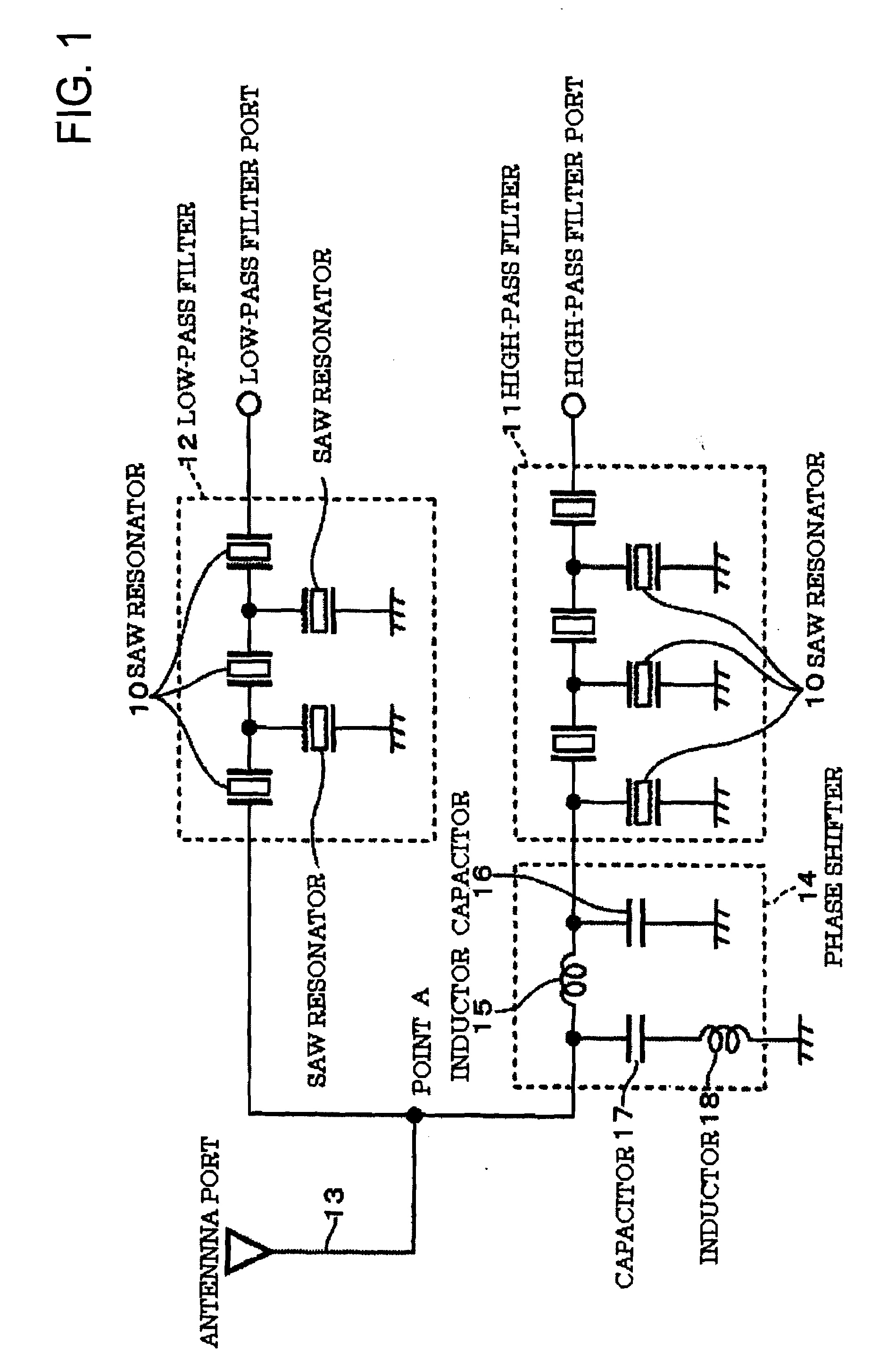
[0052]In the antenna duplexer shown by the above-described embodiments, it is possible to obtain similar function and effect by modifying the circuit configuration and the circuit component of the phase shifter or the like as below.[0053]Though the phase shifter 14, 14A to 14D are shown for the case of being inserted on the antenna port side of the high band side filter 11, a circuit configuration being directly connected to the antenna port is adopted.[0054]Though the phase shifter is embedded in the antenna duplexer, it can be externally fitted.[0055]Though the circuit configurations of the high band side filter and the low band side filter are all ladder shaped, other shapes can be adopted.[0056]A piezoelectric substrate forming a high band side filter and a low band side filter may be a wafer for a SAW device having a piezoelectric function starting with LiTaO3, LiNbO3 and quartz crystal.[0057]The inductor and the capacitor forming a phase shifter can be formed with a lumped-con...


PUM


Abstract

In an antenna duplexer including a high band side filter, a low band side filter, and a phase shifter in a low pass configuration inserted between the high band side filter and an antenna port and taking phase matching of both filters, a resonance inductor resonating with a capacitor on the antenna port side is provided to obtain a attenuation characteristic in an optional band in an out-of-pass band of both filters by the resonance. For instance, the maximum attenuation is held at twice of the center frequency fL of a pass band of the low band side filter. The LC resonance circuit configuration can be desirably modified into a configuration such that a resonance capacitor is provided to an inductor in a phase shifter having a high band side filter configuration.

Description

BACKGROUND OF THE INVENTION[0001]1. Field of the Invention[0002]The present invention relates to an antenna duplexer in which two filters of a high band side filter and a low band side filter are connected to an antenna port, and in particular relates to a phase shifter reducing interference between both filters.[0003]2. Description of the Related Art[0004]This kind of antenna duplexer is used as a duplexing means for transmitting and receiving waves in a high frequency wireless communication device such as a mobile communication terminal such as a cellular phone, a PHS, or a wireless LAN, or the like. A SAW (surface acoustic wave) filter is used for a high band side filter and a low band side filter. One of the high band side filter and the low band side filter is allocated to a transmitting side and the other is allocated to a receiving side, and both filters pass through only high frequency signals each having a specific frequency band and block signals of other frequency bands. ...

Claims


Application Information

Patent Timeline
IPC IPC(8): H03H9/72H01Q1/50
CPCH03H9/725
Inventor TERADA, SATOSHIHIROCHO, TOSHIKAZU
Owner NIHON DEMPA KOGYO CO LTD
Why Eureka
Try Eureka