
System, method, and apparatus for controlling and sealing airflow around disk drive bypass walls

a technology of bypass wall and airflow, which is applied in the direction of electric apparatus casings/cabinets/drawers, instruments, casings/cabinets/drawers details, etc., can solve the problems of loss of valuable air pressure, loss of air flow efficiency inside the bypass channel itself, and significant impact on the performance of the controllable air flow within the disk drive. , to achieve the effect of reducing the thickness of the gask

Active Publication Date: 2008-12-25
WESTERN DIGITAL TECH INC
View PDF8 Cites 4 Cited by
  • Summary
  • Abstract
  • Description
  • Claims
  • Application Information

AI Technical Summary

Benefits of technology

[0006]Embodiments of a system, method, and apparatus for controlling and sealing airflow around bypass walls in disk drives. For example, a gasket such as a bead of form-in-place gasket (FIPG) may be used to seal between the upper edge of the cover and the bypass wall. The invention may be readily extended to seal between the cover and the slit shroud, spoiler, filter, etc. Some embodiments do not require a compression ratio to form an adequate seal, but only a minimum compression from line contact to a low compression amount that only slightly reduces a thickness of the gasket. This readily satisfied requirement avoids causing an adverse effect such as distortion in the disk drive assembly, e.g., of the arm-to-disk position.
[0007]The invention has several advantages, including the ability to increase the usable air pressure in disk drives which can increase the air flow rate through a recirculation filter. In addition, an increase in the air flow potential that can be returned to the disk stack assists in momentum and power recovery.

Problems solved by technology

Controlling the circulation of air flow within disk drives significantly impacts their performance.
However, one disadvantage for any type of air flow leakage is the loss in air flow efficiency inside the bypass channel itself.
In particular, there is a loss of valuable air pressure build up due to leakages and surface friction as the airflow is bypassed through the channel and reintroduced into the disk stack.
In particular, leakage through the gap between the bypass channel and the cover amounts to a significant pressure drop on the order of about 200 Pa, even though the separation between the components is at a realistic manufacturing tolerance of approximately 0.65 mm.

Method used


Image

  • System, method, and apparatus for controlling and sealing airflow around disk drive bypass walls
  • System, method, and apparatus for controlling and sealing airflow around disk drive bypass walls
  • System, method, and apparatus for controlling and sealing airflow around disk drive bypass walls

Examples


Embodiment Construction

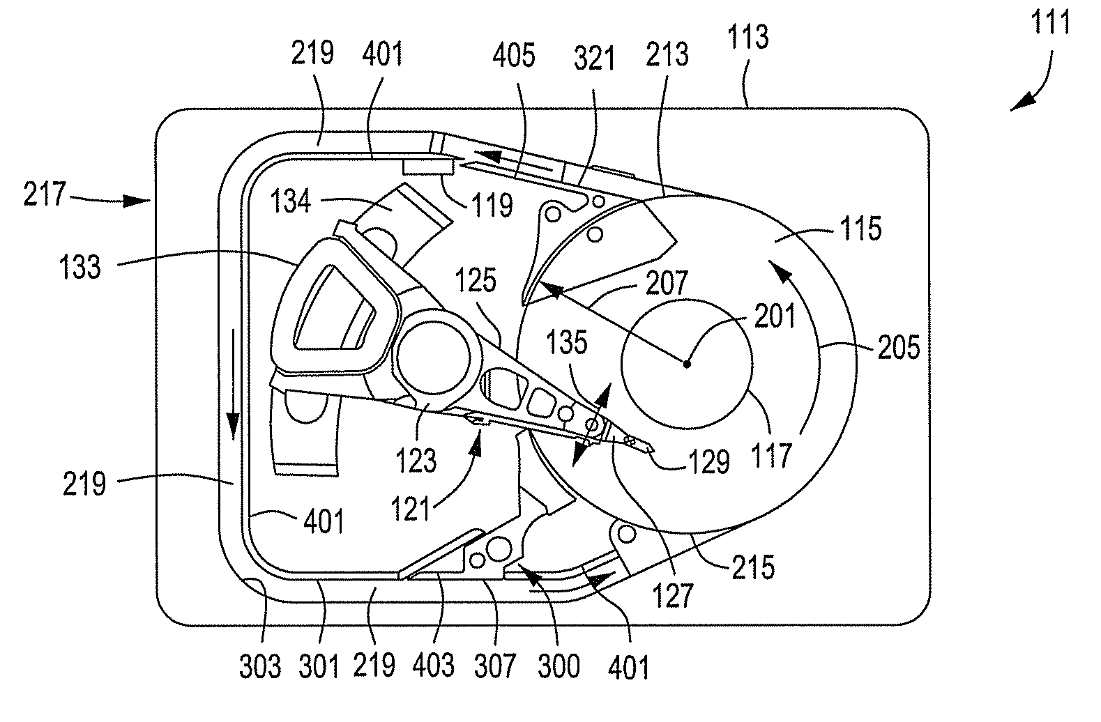
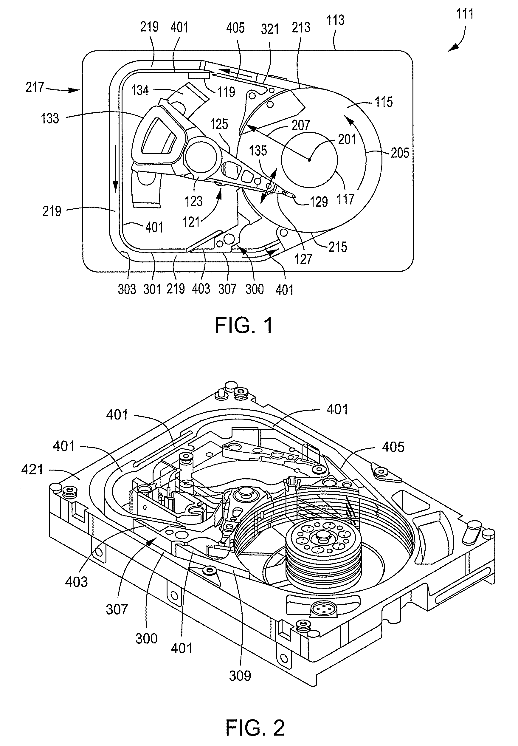
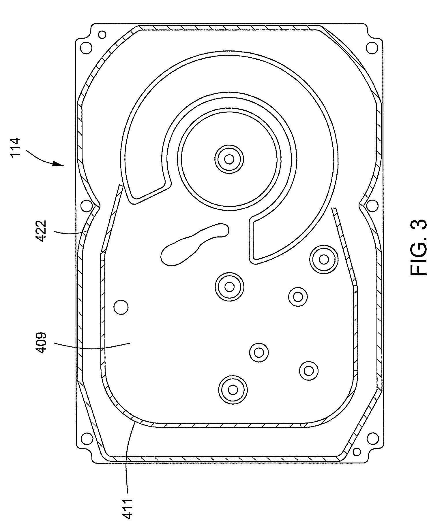
[0014]Referring to FIGS. 1-4, one embodiment of a system, method, and apparatus for an information storage system comprising a magnetic hard disk file or drive 111 for a computer system having an internal seal that is constructed in accordance with the invention is shown. Drive 111 has an outer housing including a base 113 and top cover 114 (FIGS. 3 and 4). The housing contains a disk pack having at least one media disk, e.g., a magnetic disk 115. The disks 115 are rotated (see arrow 205) by a spindle motor assembly having a central drive hub 117. An actuator 121 having one or more parallel actuator arms 125 is movably or pivotally mounted to base 113 about a pivot assembly 123. A controller 119 also is mounted to base 113 for selectively moving the arms 125 relative to disks 115.

[0015]In the embodiment shown, each arm 125 has extending from it at least one cantilevered load beam and suspension 127. A magnetic read / write transducer or head is mounted on a slider 129 and secured to a...


PUM


Abstract

A seal is formed between bypass walls and a cover for a disk drive to improve control and regulation of airflow in the disk drive. The seal is formed with a gasket comprising a bead of form-in-place gasket between the upper edge of the bypass wall and the cover. The seal also may be formed between the cover and the slit shroud, spoiler, and filter. Minimum compression of the gasket is required to form the seal.

Description

BACKGROUND OF THE INVENTION[0001]1. Technical Field[0002]The present invention relates in general to controlling air flow circulation in disk drives and, in particular, to an improved system, method, and apparatus for controlling and sealing airflow around bypass walls in disk drives.[0003]2. Description of the Related Art[0004]Controlling the circulation of air flow within disk drives significantly impacts their performance. Some types of disk drives are equipped with an aerodynamic architecture that utilizes a bypass channel to control, regulate, and advantageously circulate the air flow. Disk drives with full bypass channels employ designs that have intentional air flow leakage along some portions of the air flow path, such as a cooling slot that is adjacent the voice coil motor (VCM), air filter implementation, and a gap between the edges of the bypass channel walls and the cover of the disk drive. Advantages for intentional leakage include enhancement of certain overall flow ci...

Claims


Application Information

Patent Timeline
IPC IPC(8): G11B33/14
CPCG11B25/043G11B33/1466G11B33/1486
Inventor CHAN, ANDRE S.CHIANG, CHISINHENDRIKS, FERDINANDJOHNSON, BRAD VAUGHN
Owner WESTERN DIGITAL TECH INC
Learn More