Electric side-window roll-up shade

Inactive Publication Date: 2008-12-25
BOS
View PDF2 Cites 5 Cited by
  • Summary
  • Abstract
  • Description
  • Claims
  • Application Information

AI Technical Summary

Benefits of technology

[0011]The use of a cord running around the window has the advantage that, independent of the direction of motion, only tensile forces, which must be applied by the electric motor, are exerted on the cord. If the cord were not guided around the window, then only the extension motion of the shade could be achieved with the help of the cord, while the retraction would take place only by the spring motor, which would necessitate the spring motor also being required to overcome the friction force that the cord undergoes. In contrast, in the arrangement according to the invention, the spring motor must apply only the force that is necessary to wind up the roll-up shade or to keep it sufficiently tight during operation. The friction force that the cord undergoes during the return of the roll-up shade is transmitted from the taut cord section or return cord section to the drive motor. The cord has the additional advantage that it can also be effectively deflected around small radius curvatures, like those that appear, for example, in the upper corner of the window frame.
[0015]So that the cord always remains sufficiently tight independent of the temperature and the affect of moisture so there is no free travel, it is advantageous if the ends of the cord are connected to each other by means of a tensile spring. Another possibility is for the ends of the cord to be fixed to a rope pulley, wherein, in turn, one end is spring-biased.

Problems solved by technology

A low-lying sun both at sunrise and also at sunset can lead to glare on the driver according to the orientation of the vehicle to the sun.
The sun shining from the side also can interfere with the driver's vision, and to prevent such side glare it is known to use narrow roll-up sun shades, which are arranged in the upper regions of the side windows.
Accordingly, it is difficult for the driver to grip and pull out the roll-up shade.
On the other hand, the space for accommodating the drives for the window shades is very limited, because the width of the window frame should not be increased by the drives.

Method used


Image

  • Electric side-window roll-up shade
  • Electric side-window roll-up shade
  • Electric side-window roll-up shade

Examples


Embodiment Construction

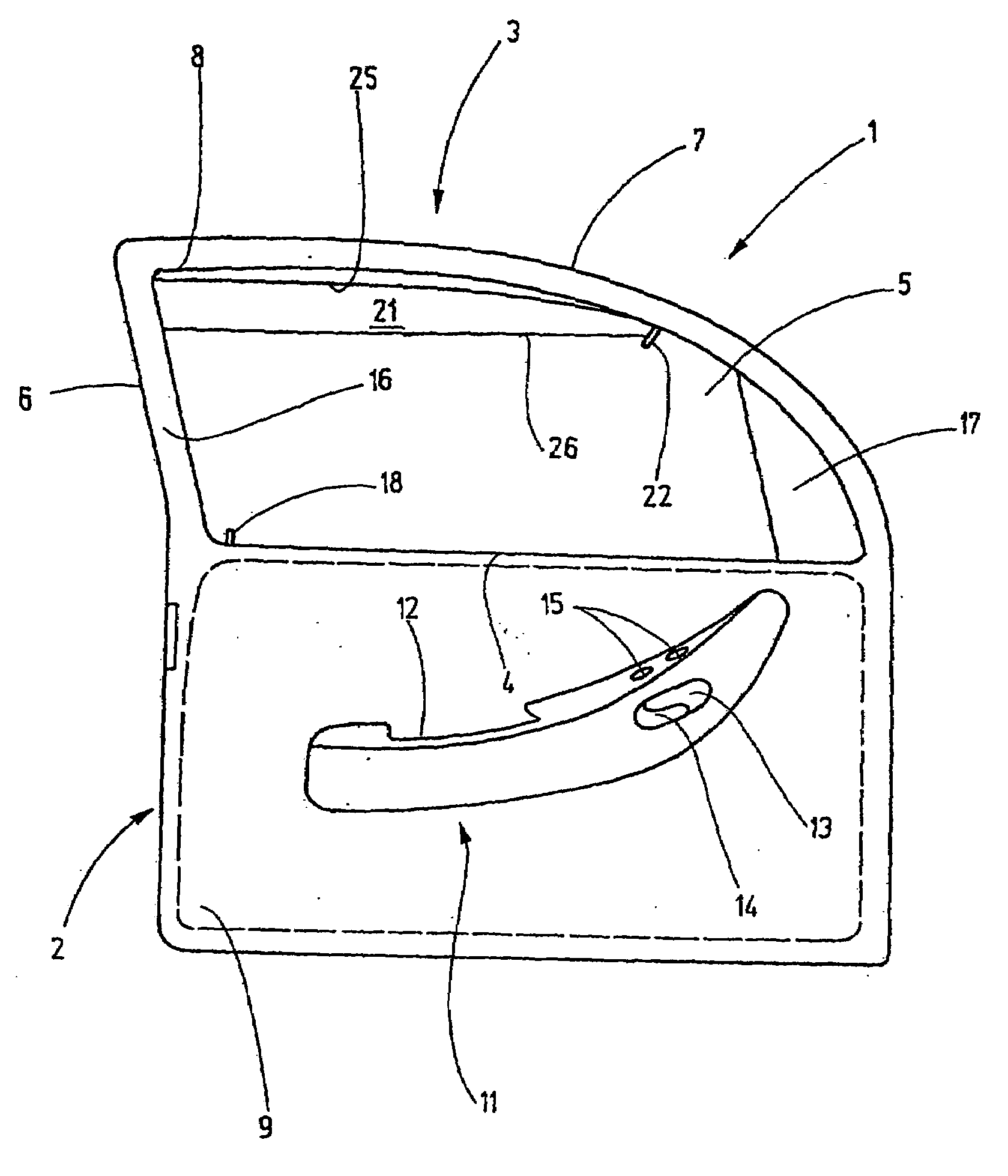
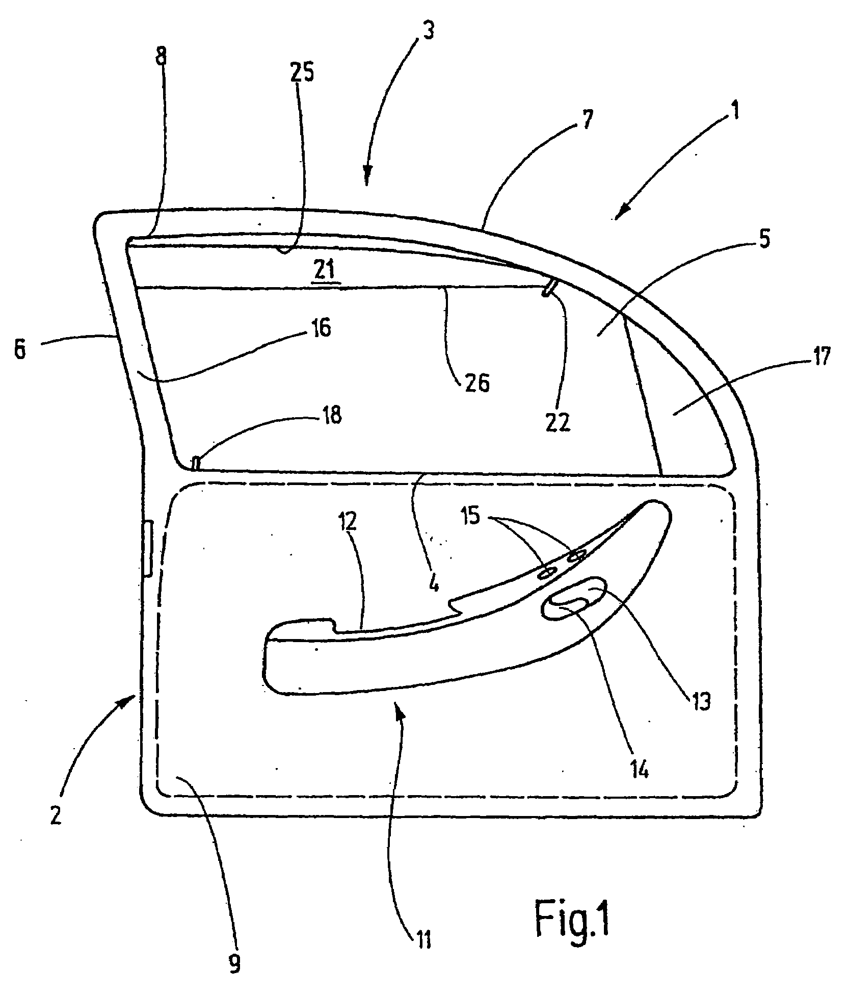
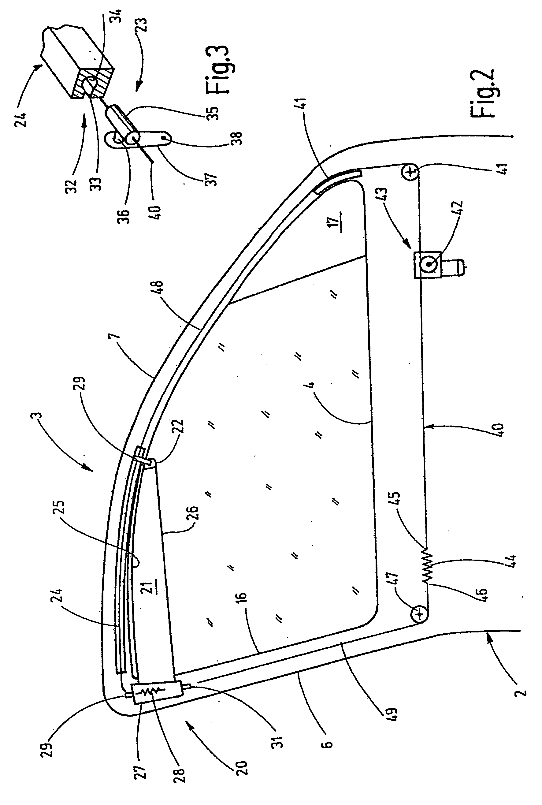
[0024]Referring now more particularly to the drawings, there is shown an illustrative motor vehicle door having a side window roll-up shade in accordance with the invention. FIG. 1 shows a view toward the inside of a left front door 1 of a motor vehicle. A lower door body 2 can be seen, over which a window frame 3 spans in an arc shape. Together with a top edge 4 of the door body 2 (FIG. 2), the window frame 3 defines a window opening 5. The frame 3 includes a rear frame part 6 and a top frame part or section 7, which merge together at 8 with an inner edge.

[0025]The rear frame part 6 leads from the inner corner 8 to the top edge of the body 2 and opens there into the door body 2. The top frame section 7 leads from the inner corner 8 to the front edge of the door and extends in an arc before it similarly opens into the door body 2.

[0026]For purposes herein, when the frame or body is discussed, hollow structures are designated, in which the individual door installed components, such a...


PUM


Abstract

A side-window roll-up shade for the front doors of motor vehicles which has a relatively short wind-up shaft housed in the region of a back edge of the window in the door frame. A short guide rail extends above the top edge of the window for guiding a slide, which is connected to a tip of the roll-up shade. For driving the roll-up shade, an electric drive with a cord is provided, with the cord extending around the window opening as a closed loop.

Description

CROSS-REFERENCE TO RELATED APPLICATIONS[0001]This patent application claims the benefit of German Patent Application No. 102007028585.1-42, filed on Jun. 19, 2007.FIELD OF THE INVENTION[0002]The present invention relates generally to roller shade assemblies, and more particularly, to a motor driven roller shade assembly for the side windows of motor vehicles.BACKGROUND OF THE INVENTION[0003]A low-lying sun both at sunrise and also at sunset can lead to glare on the driver according to the orientation of the vehicle to the sun. Glare coming from the front can be prevented by the driver through the use of a conventional sun visor, which is hinged on the ceiling above the windshield that the driver folds down when needed.[0004]The sun shining from the side also can interfere with the driver's vision, and to prevent such side glare it is known to use narrow roll-up sun shades, which are arranged in the upper regions of the side windows. These roll-up shades include wind-up shafts mounte...

Claims


Application Information

Patent Timeline
IPC IPC(8): B60J1/20
CPCB60J1/2025B60J1/2072B60J1/2086B60J3/00B60J3/02
Inventor LEKAR, JAN
Owner BOS
Why Eureka
Try Eureka