
Disc cleaning mechanism and disc cleaning device

Inactive Publication Date: 2008-12-25
HITACHI HIGH-TECH CORP
View PDF2 Cites 9 Cited by
  • Summary
  • Abstract
  • Description
  • Claims
  • Application Information

AI Technical Summary

Benefits of technology

[0012]An object of the present invention is to solve such problems in the prior art and to provide a disc cleaning mechanism and a disc cleaning device in which in a scrub cleaning of cleaning discs while catching each of the discs between adjacent brushes in a plurality of brushes mounted on a rotary shaft, the cleaning efficiency of the discs by the brushes is enhanced by efficiently cleaning the brushes for cleaning the discs with brush cleaner circular plates.
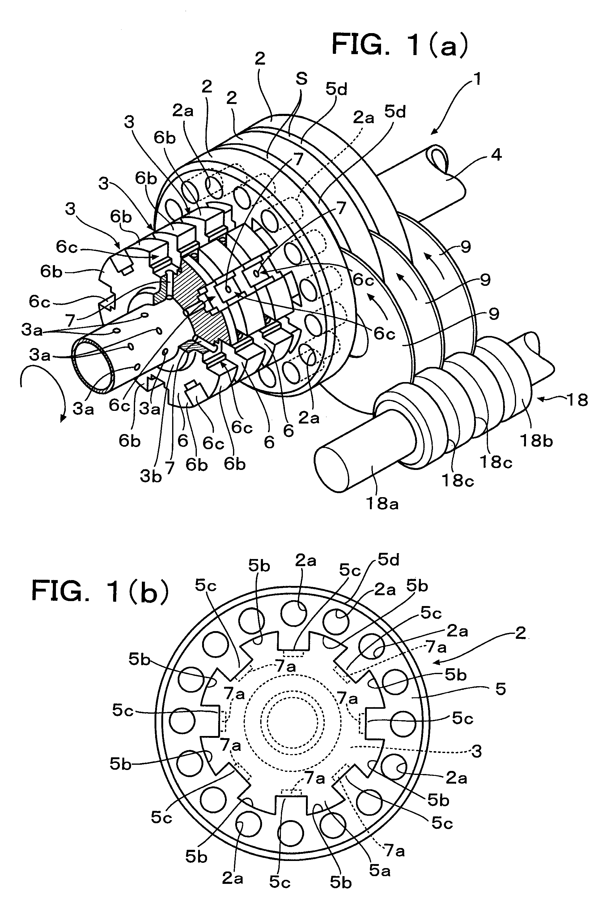
[0018]In particular, when circumferential grooves are provided on the core roller so as to engage respectively with the outer circumferences of the discs and of the brush cleaner circular plates, the dirt material or the dirt scum drops into the circumferential grooves through an action of centrifugal force by the discs, the dirt material or the dirt scum can be further easily discharged.
[0019]As a result, according to the present invention, the cleaning efficiency of the circular plate brushes for cleaning the discs can be enhanced by the brush cleaner circular plates, thereby, the cleaning efficiency of the discs by the circular plate brushes can be enhanced.

Problems solved by technology

In the scrub cleaning device in which many numbers of circular plate brushes are stacked along on the rotary shaft and the discs are cleaned while catching the discs between adjacent circular plate brushes, there arises a problem that dirt is likely to accumulate between the circular plate brushes or dirt is likely to remain on the brushes.
However, dirt material or dirt scum caught between the circular plate brushes is hard to remove.
The reason for this is thought that since the gap between the circular plate brushes of porous sponge is narrow or both are closely touched, it is difficult to scrub out the dirt material or the dirt scum, even when the brush cleaner circular plates are inserted therebetween.
For this reason, problems arise that the disc cleaning efficiency decreases, parts of brush faces are likely to wear and the exchange frequency of the circular plate brushes increases.
Therefore, it is conceived to clean the circular plate brushes by feeding cleaning liquid to the circular plate brushes from the side of the rotary shaft by making use of the technology disclosed in JP-A-9-291188, however, since it is difficult to open and close the stacked circular plate brushes in the axial direction, even if the cleaning liquid is fed to the circular plate brushes from the side of the rotary shaft, the dirt material or the dirt scum deposited between the circular plate brushes cannot be flown out by the cleaner liquid fed to the circular plate brushes from the side of the rotary shaft and cleaning of the circular plate brushes themselves cannot be effected sufficiently.

Method used


Image

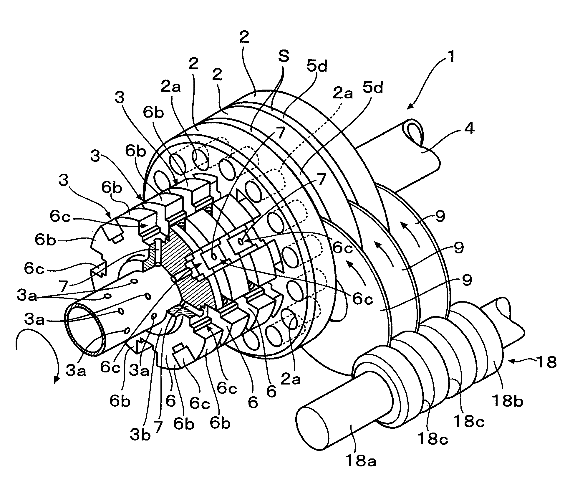
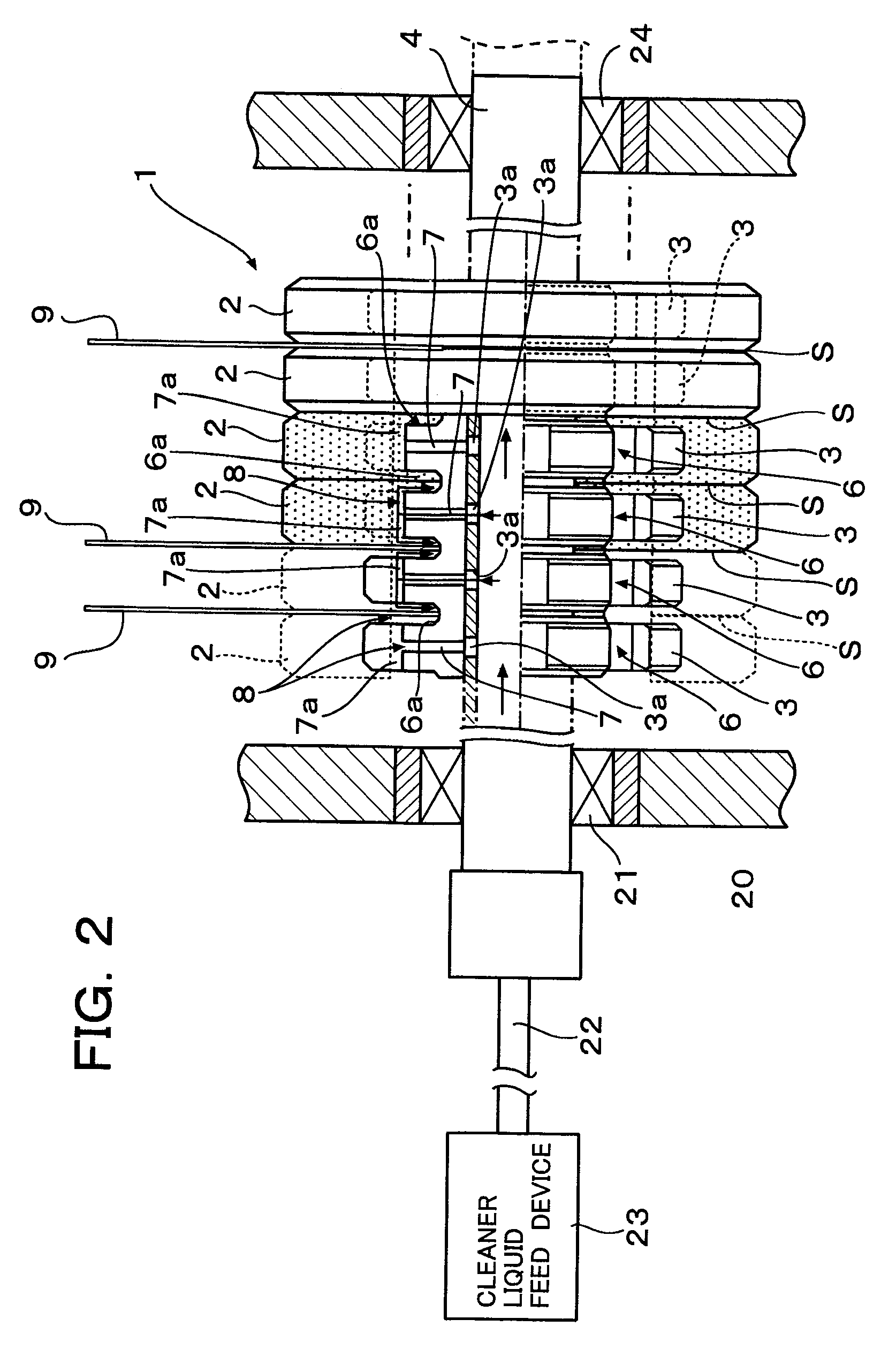
  • Disc cleaning mechanism and disc cleaning device
  • Disc cleaning mechanism and disc cleaning device
  • Disc cleaning mechanism and disc cleaning device

Examples


Embodiment Construction

[0025]Herein below, in the respective drawings, same constitutional elements are assigned of same reference numerals.

[0026]FIG. 3 is a vertically cross sectioned view for explaining a disc cleaning device, reference numeral 10 is a disc cleaning device, 10a is a base housing of the disc cleaning device 10 and 10b is an upper cover of the disc cleaning device 10.

[0027]Numeral 1 is a rotatable brush unit and is constituted by such as circular plate brush (rotatable brush) 2, ring shaped core roller 3 (see FIG. 1(a)) and a hollow shaft 4 to which many numbers of core rollers 3 are fitted and secured. In the rotatable brush unit 1, passages (as will be explained later) are formed where cleaner liquid flows out from holes 3a (see FIG. 1(a)) bored in the hollow shaft 4 to the core rollers 3. Further, in this embodiment, the many numbers of core rollers 3 and the hollow shaft 4 are integrated and constitute a single roller rotating with the hollow shaft 4 serving as a rotary shaft.

[0028]As...


PUM


Abstract

In the present invention, cleaner liquid flow passages for discharging cleaner liquid from a rotatable brush unit are formed in a rotatable brush unit. The cleaner liquid flow passages are formed as passages wherein the cleaner liquid fed to a hollow portion in a rotary shaft flows to openings in brush cleaner circular plates via lateral grooves provided around the outer circumference of a core roller and along the axial direction. A cleaner liquid fed to discs from a cleaner nozzle contains dirt when the discs are cleaned and the same is sucked into the cleaner liquid passages and the dirt is discharged from the rotatable brush unit.

Description

FIELD OF THE INVENTION[0001]The present invention relates to a disc cleaning mechanism and a disc cleaning device, and more specifically, in a disc cleaning device that performs scrub cleaning of discs (circular plates) such as hard discs, wafers and optical discs with circular plate brushes, the present invention relates to a disc cleaning mechanism and a disc cleaning device that through provision of brush cleaner circular plates for cleaning the brushes having cleaner liquid discharge openings, cleaning of the circular plate brushes is performed efficiently together with cleaning of the discs and thereby cleaning efficiency of the discs with the circular plate brushes is enhanced.BACKGROUND ART[0002]For example, in a case of such as substrates for hard discs, cleaning of the discs has been performed after the process of such as grinding, polishing, spattering and plating therefor. For the cleaning of discs such as hard discs and wafers, a plurality of cleaning processes and dryin...

Claims


Application Information

Patent Timeline
IPC IPC(8): A47L25/00
CPCG11B23/505H01L21/67005H01L21/67046
Inventor SHIZAWA, NORITAKE
Owner HITACHI HIGH-TECH CORP
Learn More