
Humidity control and air conditioning

a technology of humidity control and air conditioning, applied in the direction of defrosting, heating types, domestic cooling apparatus, etc., can solve the problems of reducing the effectiveness of heat transfer to an evaporator coil, or both

Inactive Publication Date: 2008-12-18
NORDYNE
View PDF99 Cites 62 Cited by
  • Summary
  • Abstract
  • Description
  • Claims
  • Application Information

AI Technical Summary

Benefits of technology

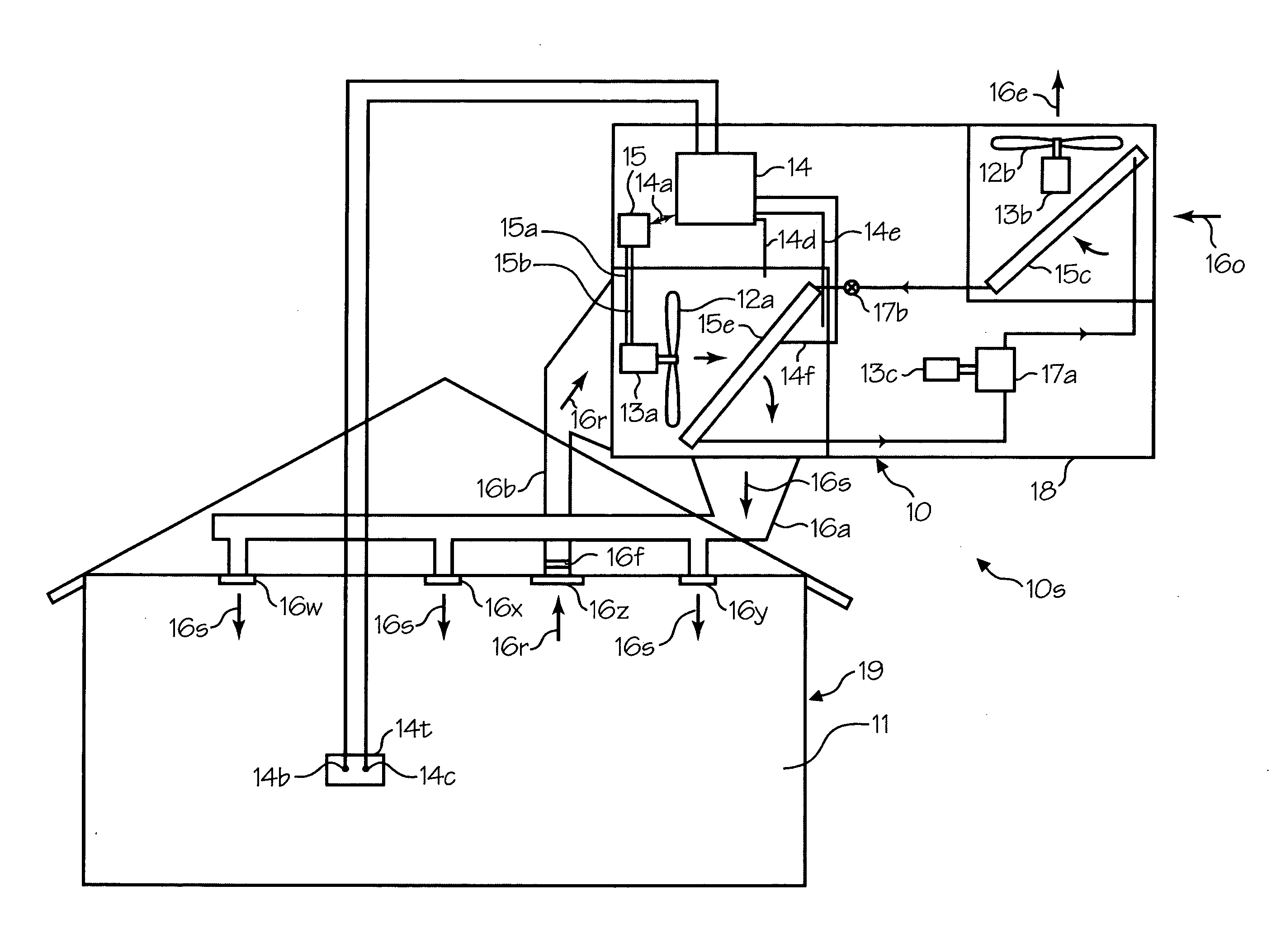
[0007]Various embodiments provide equipment, systems, and methods that are reasonably inexpensive, utilize existing components to at least some degree, are reasonably reliable, and can reasonably be placed into service by typical installation personnel, for example, typical service personnel in residential installations. Further still, particular embodiments provide equipment, systems, and methods that control or maintain (at least to some extent) humidity within desired ranges or toward desired goals. Different embodiments may provide for reduced energy consumption in comparison with certain alternatives, may provide for reduced noise, may avoid insufficient or excessive airflow rates, may provide for sufficient airflow through evaporator coils to prevent frost formation, or a combination thereof, as further examples.
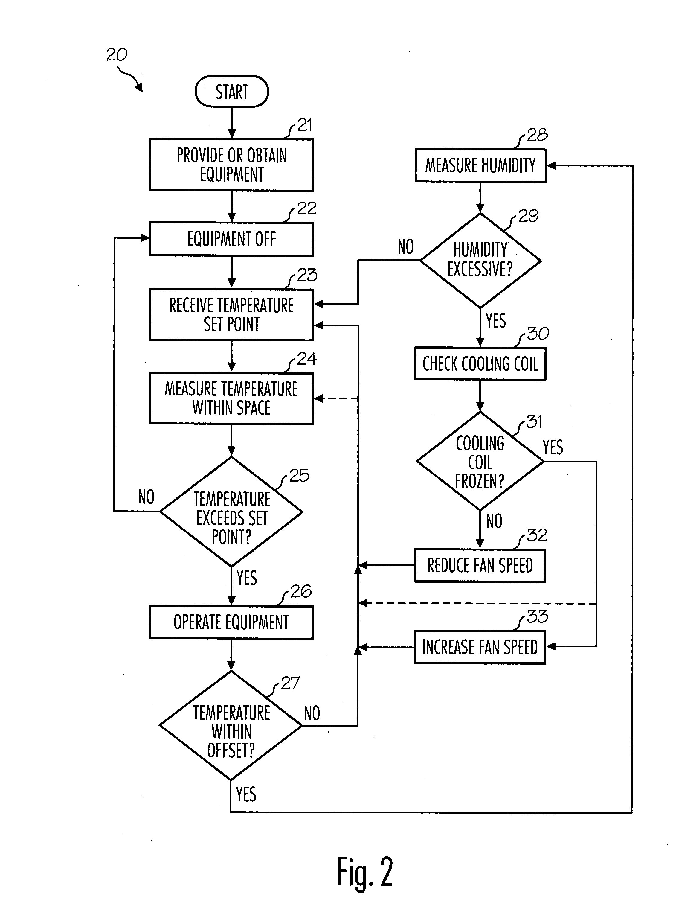
[0009]In some such embodiments, the second condition is the temperature at the cooling coil, for example. In addition, in a number of these embodiments, the controller is configured to cause the first variable-speed drive system to reduce the speed of the first electrical motor in response to an excessive humidity condition sensed by the first sensor. Furthermore, in certain embodiments, the controller is configured to cause the first variable-speed drive system to stop reducing the speed of the first electrical motor to avoid frost formation on the cooling coil, and in some embodiments, the controller is configured to cause the first variable-speed drive system to actually increase the speed of the first electrical motor to avoid frost formation on the cooling coil.

Problems solved by technology

However, it has also been known that humidity can cause frost formation on evaporator coils, and such frost formation has, on more than one occasion, blocked airflow through the evaporator coil, reduced the effectiveness of heat transfer to an evaporator coil, or both.

Method used


Image

  • Humidity control and air conditioning
  • Humidity control and air conditioning
  • Humidity control and air conditioning

Examples


Embodiment Construction

[0006]This invention provides, among other things, air conditioning units and systems that cool and dehumidify spaces within enclosures, and methods of controlling humidity within a space, for example, using an air conditioning unit or system. Different embodiments adjust or vary speed or torque of a blower or fan motor based on inputs from sensors within the system, using automated processes, or both, for example. Various embodiments of the invention provide as an object or benefit that they partially or fully address one or more of the needs, potential areas for improvement or benefit, or functions described herein, for instance. Specific embodiments provide as an object or benefit, for instance, that they at-least partially provide for control of humidity within a space, provide for control of HVAC equipment or systems, or provide specific air conditioning systems, equipment, or units, or a combination thereof, for example. In many embodiments, a controller is used to control var...


PUM


Abstract

Air conditioning systems that cool and dehumidify spaces within enclosures, buildings having such systems, and methods of controlling humidity within a space. Embodiments adjust speed of a blower or fan motor based on inputs from sensors within the system, using automated processes, to reduce airflow rates to provide for lower temperatures of the cooling coil and to increase the ratio of latent to sensible heat transfer. Fan speeds may be increased as appropriate to avoid frost formation on the cooling coil, to give priority to cooling when temperatures within the space are high, or periodically to provide for mixing within the space.

Description

FIELD OF INVENTION [0001]This invention relates to systems and methods for controlling humidity, heating, ventilating, and air-conditioning (HVAC) equipment, systems and methods, and control equipment. Specific embodiments relate to mass-produced air conditioning units, for example, for residential applications, and to their controls.BACKGROUND OF THE INVENTION [0002]Heating, ventilating, and air-conditioning (HVAC) systems have been used to ventilate and maintain desirable temperatures within spaces such as buildings, for occupants to live and work, for example. Air conditioning units have been known to remove humidity from the air, as well as reducing the temperature of the air, and humidity reduction has contributed to making spaces within enclosures more comfortable, particularly in hot and humid climates or conditions. However, it has also been known that humidity can cause frost formation on evaporator coils, and such frost formation has, on more than one occasion, blocked air...

Claims


Application Information

Patent Timeline
Patent Type & Authority Applications(United States)
IPC IPC(8): F25D21/04F25D17/06
CPCF24F3/147F24F11/0079F24F2011/0087Y02B30/746F24F11/41F24F11/77Y02B30/70
Inventor HERZON, AARON D.
Owner NORDYNE
Learn More