
Siphon for Delivery of Liquid Cryogen from Dewar Flask

a technology of liquid cryogen and siphon, which is applied in the direction of liquid bottling, packaging goods, special packaging, etc., can solve the problems of not teaching or describing the above background art references of dewar flask siphon, which reduces the amount of gas, and achieves the effect of high quality of liquid cryogen

Inactive Publication Date: 2008-12-18
ICECURE MEDICAL
View PDF5 Cites 12 Cited by
  • Summary
  • Abstract
  • Description
  • Claims
  • Application Information

AI Technical Summary

Benefits of technology

[0010]None of the above background art references teaches or describes a design of a Dewar flask siphon which ensures delivery of high quality of liquid cryogen even for low values of the flow rate. Furthermore, none of the above background art references teaches or describes a Dewar flask siphon which reduces the amount of gas generated from the liquid cryogen.
[0011]The present invention overcomes these drawbacks of the background art by providing a siphon system for a container such as a Dewar flask, which ensures delivery of high quality of a liquid cryogen even for low values of the flow rate.
[0012]According to preferred embodiments of the present invention, the siphon ensures delivery of a liquid cryogen with a lower proportion of the gaseous fraction as compared to other siphon / Dewar flask systems which are known in the art. The siphon comprises a central feeding conduit, which is preferably largely positioned within the Dewar flask such that at least about 50% and more preferably at least about 60%, and most preferably at least about 75% of the central feed conduit is positioned within the Dewar flask. Preferably an external (auxiliary) conduit surrounds the central feeding conduit; and, the outer upper section of this auxiliary conduit is preferably provided with a port and an adjustable valve intended to release a gaseous fraction of the cryogen contained in the annular gap between the auxiliary and central feeding conduits.

Problems solved by technology

Furthermore, none of the above background art references teaches or describes a Dewar flask siphon which reduces the amount of gas generated from the liquid cryogen.

Method used


Image

  • Siphon for Delivery of Liquid Cryogen from Dewar Flask
  • Siphon for Delivery of Liquid Cryogen from Dewar Flask
  • Siphon for Delivery of Liquid Cryogen from Dewar Flask

Examples


Embodiment Construction

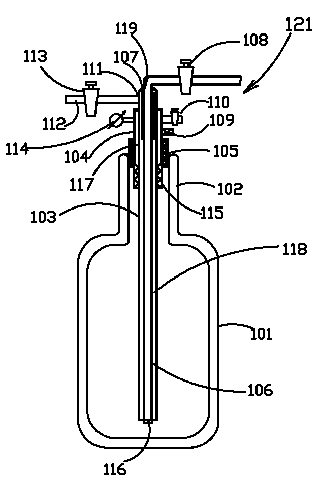
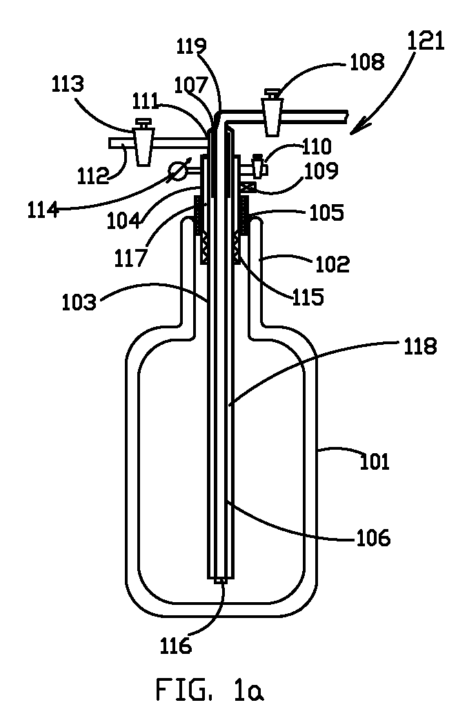
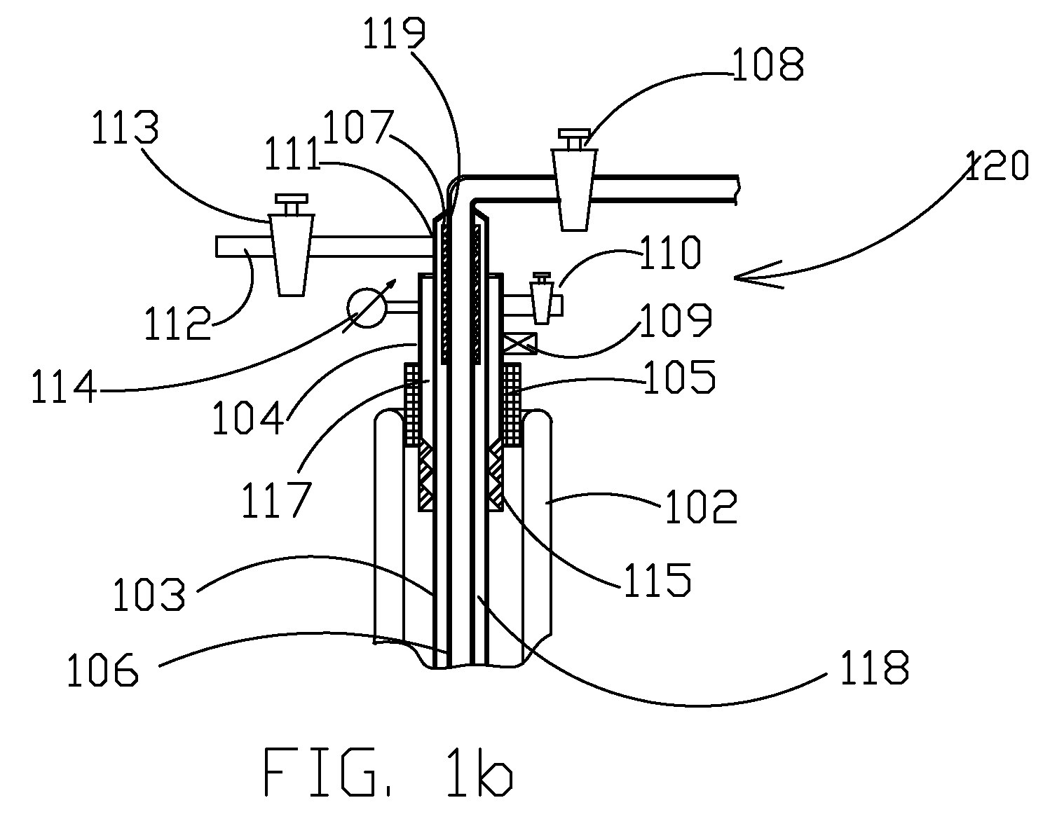
[0050]FIG. 1a and FIG. 1b show an axial cross-sectional view of an exemplary Dewar flask with a siphon installed in its neck according to preferred embodiments of the present invention, and an enlarged axial cross-sectional view of the upper section of the Dewar flask and the siphon. FIG. 1A shows a Dewar flask 101 with neck 102, which is intended to be filled with a liquid cryogen to be supplied by the siphon 121; FIG. 1B shows an expanded view of neck 102 and the upper siphon sections 120. Siphon 120 comprises an external conduit 103 and jacket 104 surrounding the external conduit 103 with gap 117 formed between them. The upper edge of jacket 104 is sealed with the external conduit 103 as shown. Siphon 121 also features an central feeding conduit 106 with gap 118 between the central feeding conduit 106 and the external conduit 103; this central feeding conduit serves for supply of the liquid cryogen to a target place. There is also a seal for sealing jacket 104 to the Dewar flask,...


PUM


Abstract

The invention involves a siphon for delivery of a liquid cryogen from a container such as a Dewar flask. The siphon ensures delivery of a liquid cryogen with a lower proportion of the gaseous fraction. The siphon comprises a central feeding conduit, which is largely contained within the Dewar flask. There is an auxiliary conduit surrounding the central feeding conduit; the outer upper section of this auxiliary conduit is provided with an adjustable valve intended to release a gaseous fraction of the cryogen contained in the annular gap between the auxiliary and central feeding conduits. The upper section of the central feeding conduit is provided with an external layer of a porous capillary coating or with a wick; this ensures that the upper section of the central feeding conduit is continuously wetted with the liquid cryogen. This porous capillary coating prevents gasification of the liquid cryogen in the central feeding conduit. Alternatively, the problem of liquid cryogen gasification may be solved through thermal insulation of the central feeding conduit.

Description

FIELD OF THE INVENTION[0001]The invention relates to cryogen devices and, in particular, to a Dewar flask siphon which ensures delivery of a high quality of liquid cryogen even for low values of the flow rate.BACKGROUND OF THE INVENTION[0002]Siphons intended for feeding a liquid cryogen contained in a Dewar flask are known in the art, although all suffer from various drawbacks, particularly as they increase the amount of gas generated from the liquid cryogen as it becomes heated.[0003]For example, Tsals (U.S. Pat. No. 6,012,453) describes an apparatus that provides for withdrawal of the liquid contents from a closed container independent of the spatial orientation thereof. The liquid withdrawal apparatus includes flexible withdrawal conduits disposed inside the container and in fluid flow communication with external heat exchangers. The heat exchangers serve to transfer heat to the withdrawn liquid to thereby provide a breathable gas mixture. The upstream end of the withdrawal condu...

Claims


Application Information

Patent Timeline
Patent Type & Authority Applications(United States)
IPC IPC(8): F17C6/00
CPCF17C9/00F17C2205/0358F17C2221/01F17C2223/0161F17C2223/033F17C2223/047F17C2225/0161F17C2250/032F17C2250/0408F17C2250/043F17C2260/044F17C2265/012F17C2270/05
Inventor LEVIN, ALEXANDERTOUBIA, DIDIERKAGANOVICH, MIRON
Owner ICECURE MEDICAL
Learn More