
Blood acess apparatus and method

Inactive Publication Date: 2008-12-11
LIFESHIELD SCI
View PDF18 Cites 53 Cited by
  • Summary
  • Abstract
  • Description
  • Claims
  • Application Information

AI Technical Summary

Benefits of technology

[0009]Typical vascular grafts are porous, with small interconnecting pores or void spaces which will pass cells and fluids between the inside and outside surfaces so that tissue may grow throughout the graft wall and may cover the inside and outside surfaces of the graft. One goal is to get just the right amount of tissue growth and an endothelial lining on the luminal or interior portion of the graft, so that the antithrombotic activity of endothelium can prevent thrombosis of the vascular graft. However, pore size and structure may be limited by a requirement that the vascular graft not leak blood or plasma in significant amounts in the period after being implanted and prior to maturation. Thus, large pores which facilitate tissue ingrowth are desired, yet small pores which limit leakage are also desired, especially in a structure which may withstand repeated needle puncture for dialysis access.
[0019]Further, the blood access device of the present invention may include additional layers that may be used for controlling leakage or enhancing the useability or performance of the blood access device.

Problems solved by technology

Two major problems are thrombosis, due to lack of proper healing and endothelialization, and intimal hyperplasia, causing luminal narrowing, most commonly at or near the venous anastomosis.
However, pore size and structure may be limited by a requirement that the vascular graft not leak blood or plasma in significant amounts in the period after being implanted and prior to maturation.

Method used


Image

  • Blood acess apparatus and method
  • Blood acess apparatus and method
  • Blood acess apparatus and method

Examples


Embodiment Construction

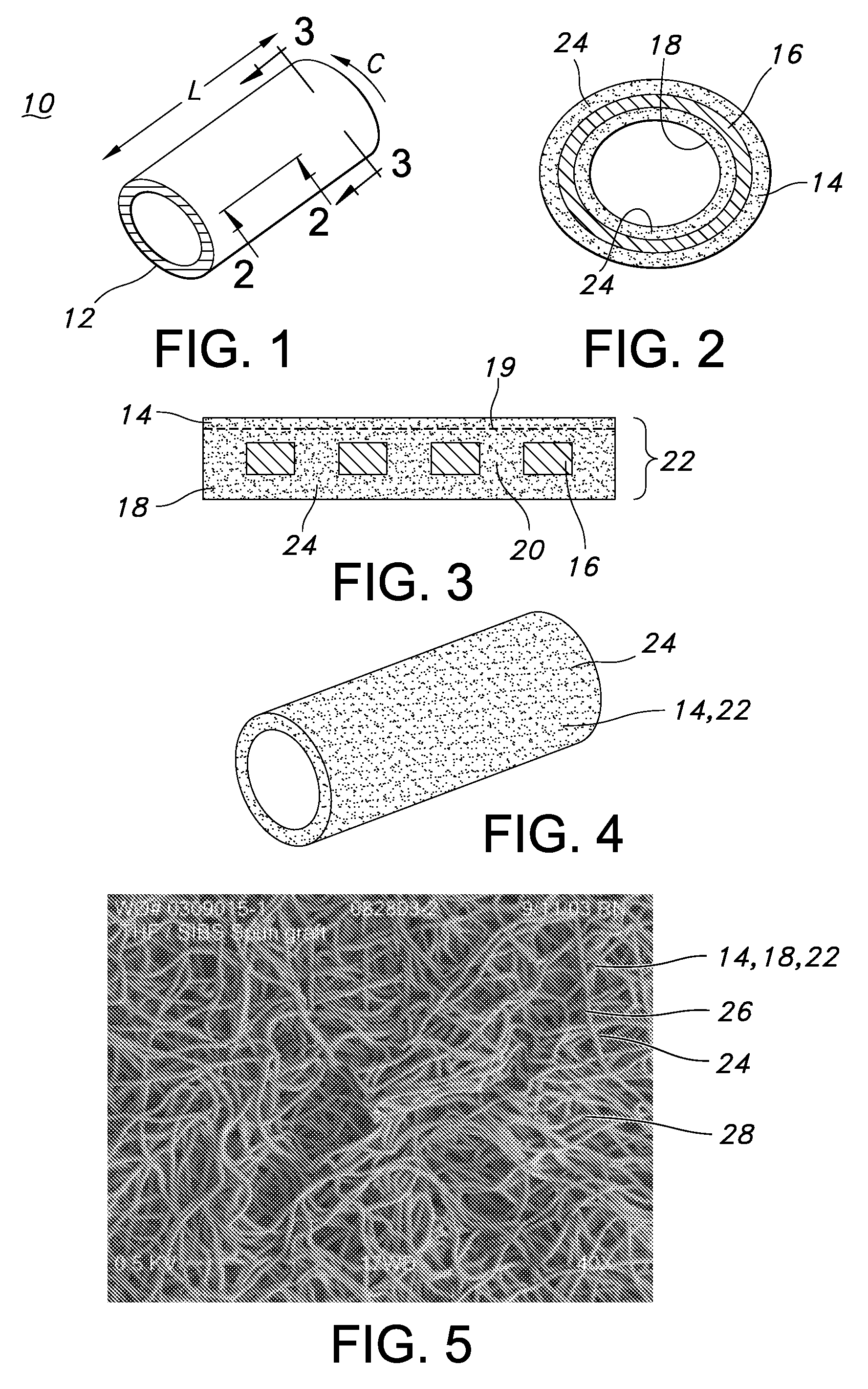
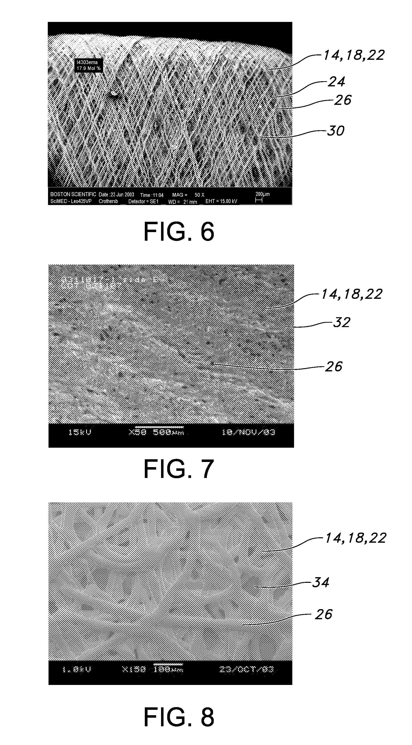
[0035]FIG. 1 is a perspective view of a blood access device 10 of the present invention. The blood access device 10 is a single lumen device defined by a cylindrical wall 12. FIG. 2 is a cross-sectional view of the of the blood access device 10 of FIG. 1 taken along the 2-2 axis. The blood access device 10 includes an external polymeric portion 14, an expandable support structure 16, and an internal or luminal polymeric portion 18. The external polymeric portion 14 and the luminal polymeric portion 18 may be the same or different. Further, the external polymeric portion 14 and the luminal polymeric portion 18 may be a unitary structure formed by the same or similar materials at or about the same time by a similar formation technique. For example, the luminal polymeric portion 18 may be formed or disposed over a mandrel (not shown), which is typically a cylindrical mandrel. The expandable support structure 16 may then be formed or disposed over the luminal polymeric portion 18. The e...


PUM

PropertyMeasurementUnit
Pore sizeaaaaaaaaaa
Pore sizeaaaaaaaaaa
Thicknessaaaaaaaaaa

Abstract

A blood access for dialysis includes a radially distensible support structure having an open lattice structure defining a support wall having interstitial open areas and defining exterior and luminal wall surfaces; a first porous polymeric portion having a plurality of pores, the first porous polymeric portion being securably disposed over at least a portion of the exterior wall portion of the support structure; a second porous polymeric portion having a plurality of pores, the second porous polymeric portion being securably disposed over at least a portion of the luminal portion of the support structure; and a biodegradable and / or bioabsorbable material disposed within the pores of the first polymeric portion and / or pores of the second polymeric portion.

Description

CROSS-REFERENCE TO RELATED APPLICATIONS[0001]This application claims the benefit of U.S. Provisional Application No. 60 / 899,601, filed Feb. 5, 2007, the contents of which are incorporated herein by reference.FIELD OF THE INVENTION[0002]The invention is related to a blood access device for use in an arteriovenous fistula to provide for blood access for dialysis. More particularly, the present invention is related to a composite material blood access device for dialysis and useful for minimizing arteriovenous fistula maturation time periods, and methods for the same.BACKGROUND OF THE INVENTION[0003]Blood access for hemodialysis is commonly achieved by placement of an arteriovenous graft. Typically, an expanded polytetrafluoroethylene (ePTFE) graft is surgically placed in the forearm with one end of the graft anstomosed to an artery and the other end of the graft anstomosed to a vein. Prior to use for blood access, the graft must generally be encapsulated by tissue. Such encapsulation,...

Claims


Application Information

Patent Timeline
IPC IPC(8): A61F2/82A61F2/84A61B17/32B23P11/00
CPCA61F2/07A61F2/82A61F2002/072Y10T29/49826A61F2/90A61F2002/075A61M1/3655
Inventor JENSON, MARK L.DRASLER, WILLIAM J.HILL, JASON P.KOKATE, JAYDEEPSOGARD, DAVID J.HAVERKOST, PAT
Owner LIFESHIELD SCI
Learn More