
Method for checking the plausibility of the position of the clutch actuator of a clutch, method for determining the touch point of a clutch, and device for carrying out the method

Active Publication Date: 2008-12-11
SCHAEFFLER TECH AG & CO KG
View PDF6 Cites 34 Cited by
  • Summary
  • Abstract
  • Description
  • Claims
  • Application Information

AI Technical Summary

Benefits of technology

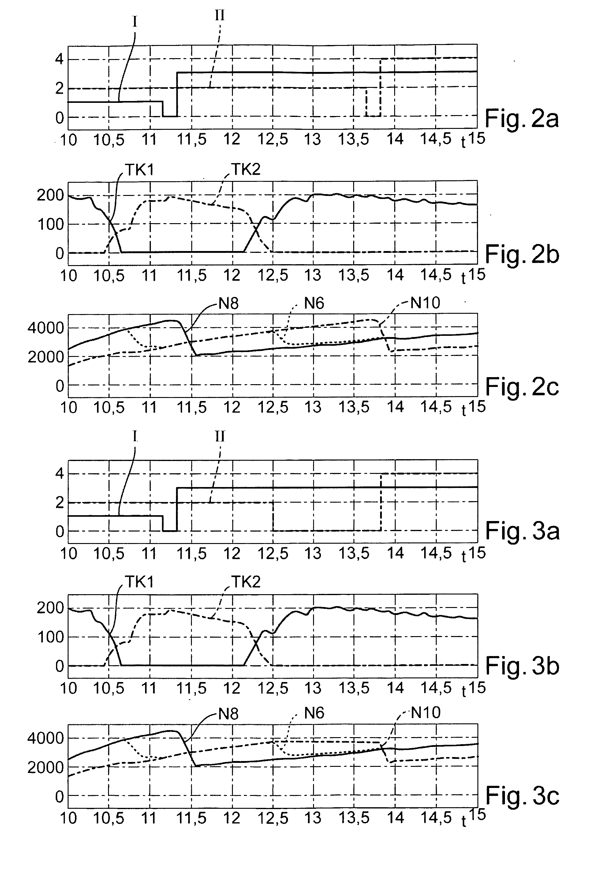
[0006]An embodiment of the present invention provides a method to reliably detect whether a particular one of the clutches of the double-clutch transmission is actually disengaged when it is supposed to have been directed to the disengaged state by a control device of the double-clutch transmission.
[0015]Likewise, before the gradual engagement begins the speed of the drive shaft can be increased, so that as the gradual engagement of the clutch assigned to the old subtransmission begins the drive shaft may be turning at a higher speed than the input shaft of the old subtransmission.

Problems solved by technology

A fundamental problem of such incremental travel measurements is their dependence on exact determination of the reference position.
This problem is exacerbated by the fact that when operating a motor vehicle one must always plan on the occurrence of error events, which can result in the absolute position of the clutch actuator or of the actuating element of the clutch, and hence also the clutch torque set by the actuator in the electronic control device, no longer being known.
That can result in safety-critical events, for example drive-off when travel is not wanted.

Method used


Image

  • Method for checking the plausibility of the position of the clutch actuator of a clutch, method for determining the touch point of a clutch, and device for carrying out the method
  • Method for checking the plausibility of the position of the clutch actuator of a clutch, method for determining the touch point of a clutch, and device for carrying out the method
  • Method for checking the plausibility of the position of the clutch actuator of a clutch, method for determining the touch point of a clutch, and device for carrying out the method

Examples


Embodiment Construction

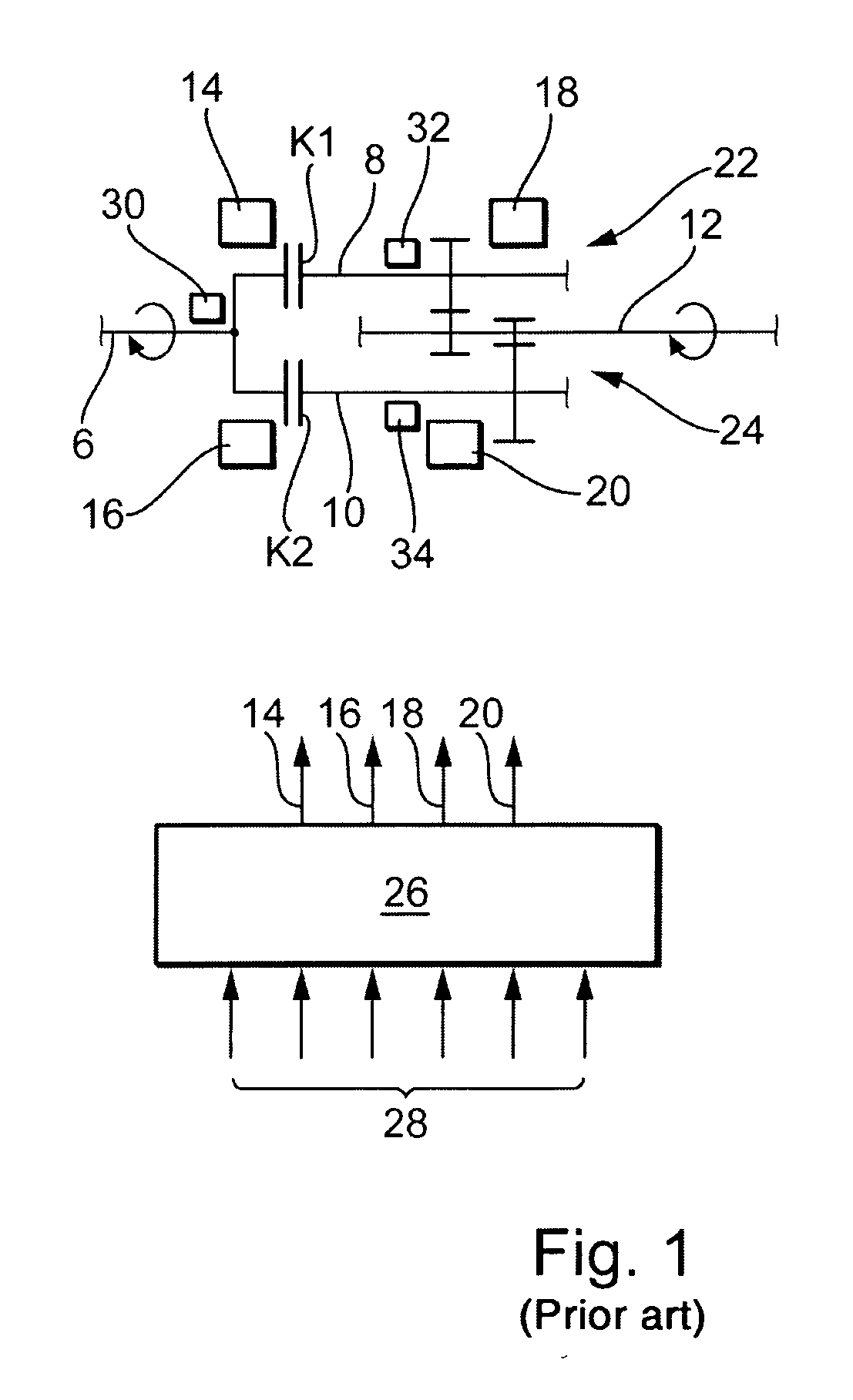
[0028]According to FIG. 1, a known double-clutch or parallel shift transmission has a drive shaft 6 driven for example by a combustion engine, which is optionally connectable with rotationally fixed connections to two input shafts 8 and 10. The flow of torque from drive shaft 6 into input shafts 8 and 10 is selectively controllable through clutches K1 and K2, respectively. Between input shaft 8 and an output shaft 12 various transmission ratios are activatable via gear pairings, only one of which is illustrated. Various gear pairings are likewise activatable between input shaft 10 and output shaft 12, only one of which is illustrated. Actuators 14 and 16 are provided to operate the clutches K1 and K2. To activate the gear pairings, for example to produce a rotationally fixed connection between the gear situated on input shaft 8 or 10 with the respective input shaft 8 or 10, which meshes with a particular gear that has a constant rotationally fixed connection with output shaft 12, ac...


PUM


Abstract

A method for checking the plausibility of an actuation position of a clutch of a double-clutch transmission operated by an actuator, including the following steps: disengaging the clutch assigned to the currently active old subtransmission and simultaneously engaging the clutch assigned to the other subtransmission to shift from the gear selected in the old subtransmission to a gear selected in the other, new subtransmission; deselecting the gear selected in the old subtransmission still during the overlapping operation of the clutches or immediately thereafter; detecting the difference between the speed of rotation of a drive shaft of the double-clutch transmission driven by a drive motor and the speed of rotation of the input shaft of the old subtransmission; and evaluating the state of the clutch assigned to the old subtransmission as disengaged when the difference in speeds of rotation exceeds a predetermined value within a predetermined time after deselection of the gear.

Description

[0001]This claims benefit of German Patent Application 10 2007 025 412.3, filed May 31, 2007, and hereby incorporated by reference herein.BACKGROUND[0002]The invention relates to a method for checking the plausibility of the position of the clutch actuator of a clutch contained in a dual clutch transmission. The invention also relates to a method for determining the touch point of a clutch operated by an actuator. In addition, the invention relates to a device for carrying out the method.[0003]In modern motor vehicles, automated clutches, i.e. clutches operated by an actuator, are being used increasingly. The position of the actuating element of the clutch or of the actuator is detected in most cases with the aid of an increment meter, which directly supplies only information about actuator travel paths just traversed, but not information about the absolute position of the actuating element. In order to find the absolute position, a referencing is necessary, in which the actuator mo...

Claims


Application Information

Patent Timeline
IPC IPC(8): B60W10/02
CPCF16D48/06F16D2500/102F16D2500/10412F16D2500/30401F16D2500/30808Y10T477/78F16D2500/5012F16D2500/5026Y10T477/753Y10T477/79Y10T477/75F16D2500/30816
Inventor EICH, JUERGENREIBOLD, EKKEHARDNGUYEN, MINH NAMPANZER, MATTHIAS
Owner SCHAEFFLER TECH AG & CO KG
Learn More