Toroidal continuously variable transmission
a technology of continuous variable transmission and toroidal, which is applied in the direction of transportation and packaging, other domestic objects, and gearing, etc., can solve the problems of reducing the production cost of the traction surface corresponding to the surface to be processed, reducing the cost of processing devices, and reducing the cost of forming the concave groov
- Summary
- Abstract
- Description
- Claims
- Application Information
AI Technical Summary
Benefits of technology
Problems solved by technology
Method used
Image
Examples
first embodiment
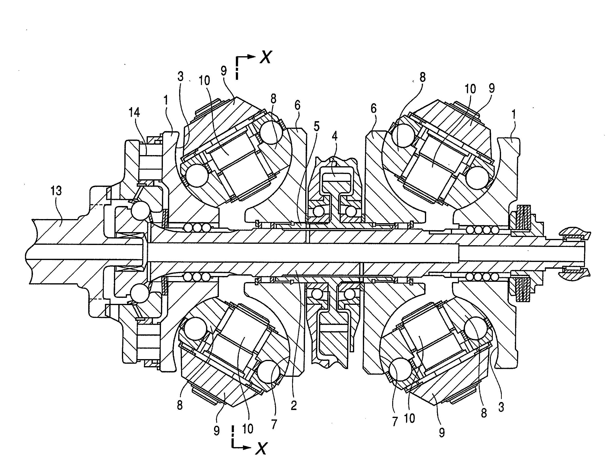
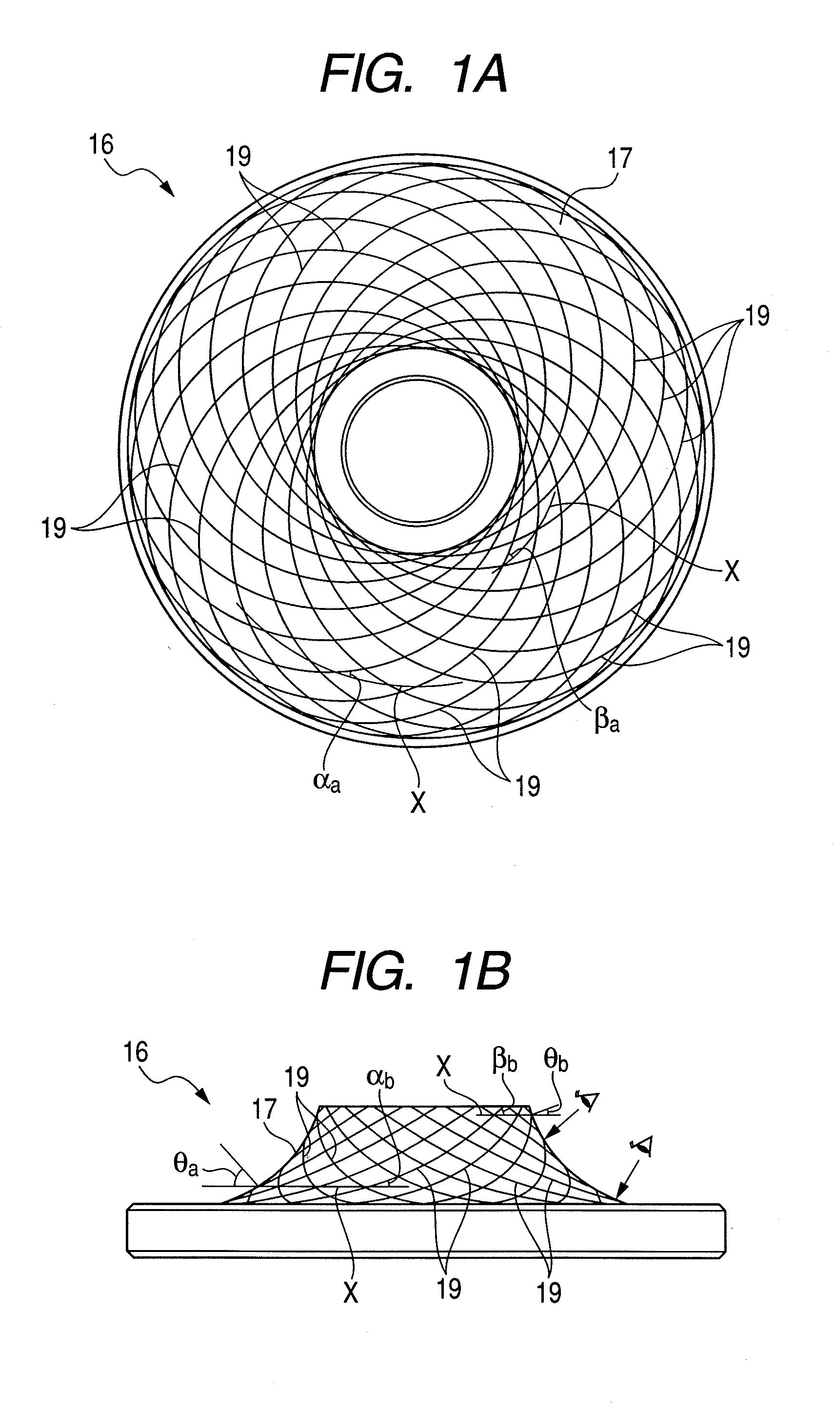
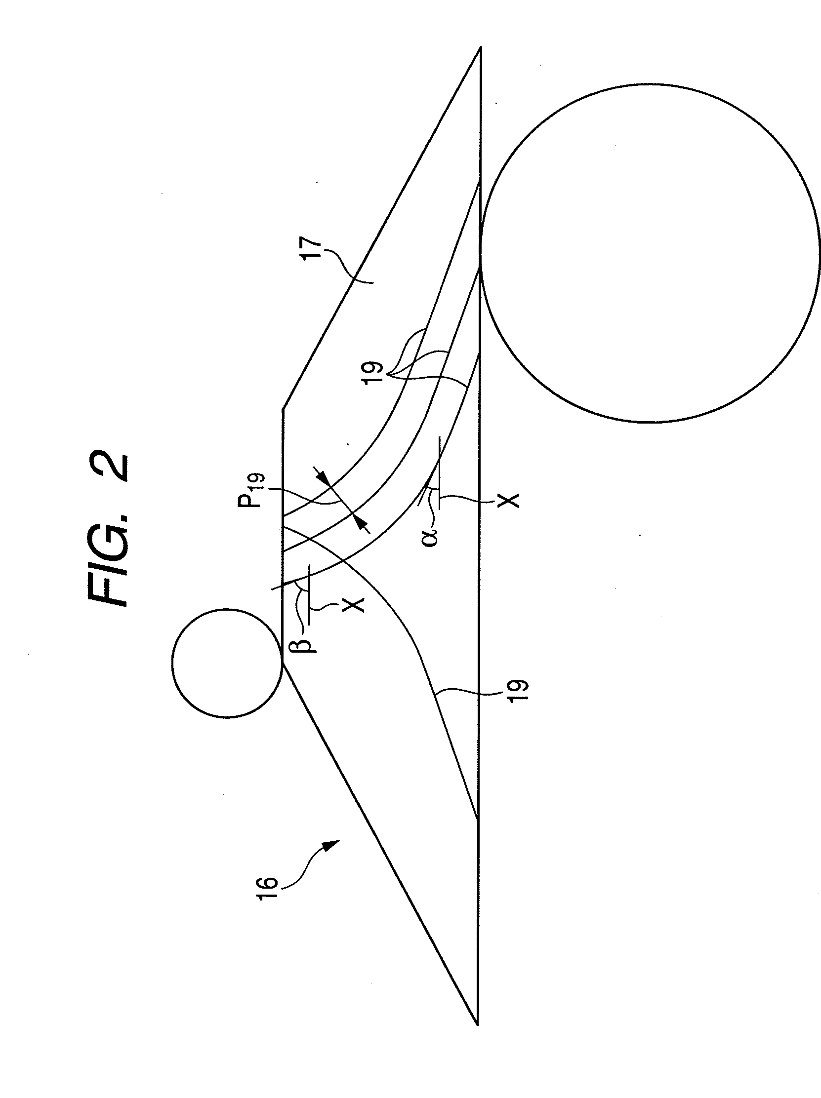
[0079]FIGS. 1 to 3 show a first embodiment of the invention. In addition, a characteristic of this embodiment is to study a principle of concave grooves 19, 20 in order to provide a structure with a plurality of concave grooves 19, 20 improving a traction coefficient while ensuring durability of a disk 16 (which corresponds to an input-side disk 1 and an output-side disk 6 shown in FIG. 9) and a power roller 8. Since the other structures and effects are the same as those of the known example described in FIGS. 9 and 10, the repetitive drawings and descriptions thereof will be omitted or described in brief. Hereinafter, a characteristic part of this embodiment will be mainly described.
[0080]In this embodiment, as shown in FIGS. 1 and 2, a plurality of concave grooves 19, 19 are formed in a whole one-side surface 17 (which corresponds to a surface shown in FIGS. 1A and 2, an upper surface shown in FIG. 1B, an input-side inner surface 3, and an output-side inner surface 7 shown in FIG....
second embodiment
[0102]FIGS. 4 and 5 show a second embodiment of the invention. In this embodiment, as shown in FIG. 4, the disk-side concave grooves 19, 19 are formed into a concentric shape (or a spiral shape) about the central shaft (rotation shaft) of the disk 16. Meanwhile, as shown in FIG. 5, the power roller-side concave grooves 20, 20 are formed so as to have angles with respect to the circumferential direction of the power roller 8 when viewed from a normal direction relative to the peripheral surface 18 of the power roller 8. Then, in this embodiment, the angles are formed such that an angle on the inner diameter side of the power roller 8 is larger than that on the outer diameter side thereof.
[0103]The other configurations, effects, and methods of forming the power roller-side concave grooves 20, 20 are the same as those of the first embodiment described above except that the concave grooves having the angles are the power roller-side concave grooves 20, 20 and the surface (the peripheral...
third embodiment
[0104]FIGS. 6 to 8 show a third embodiment. In this embodiment, in the same way as the second embodiment described above, the disk-side concave grooves 19, 19 are formed into a concentric shape (or a spiral shape) about the central shaft (rotation shaft) of disks 16a and 16b. However, in this embodiment, the disk-side concave grooves 19, 19 are formed only in a part where the peripheral surface 18 of the power roller 8 comes into rolling contact with the one-side surface 17 of the disks 16a and 16b in the axial direction in a state of a transmission gear ratio particularly necessary to ensure a traction coefficient (the disk-side concave grooves 19, 19 are not formed on the whole one-side surface 17). Specifically, as described in FIG. 9, when the transmission gear ratio between the input-side disks 1 and 1 and the output-side disks 6 and 6 is in a deceleration state, the disk-side concave grooves 19, 19 are formed only in a part where the peripheral surface 18 of the power roller 8...
PUM
| Property | Measurement | Unit |
|---|---|---|
| Angle | aaaaa | aaaaa |
| Angle | aaaaa | aaaaa |
| Angle | aaaaa | aaaaa |
Abstract
Description
Claims
Application Information
 - R&D
- Intellectual Property
- Life Sciences
- Materials
- Tech Scout
- Unparalleled Data Quality
- Higher Quality Content
- 60% Fewer Hallucinations
Browse by: Latest US Patents, China's latest patents, Technical Efficacy Thesaurus, Application Domain, Technology Topic, Popular Technical Reports.
© 2025 PatSnap. All rights reserved.Legal|Privacy policy|Modern Slavery Act Transparency Statement|Sitemap|About US| Contact US: help@patsnap.com


