
System for Dehydrating and Cooling a Produced Gas to Remove Natural Gas Liquids and Waste Liquids

a technology of produced gas and dehydrating system, which is applied in the direction of gaseous fuels, lighting and heating apparatus, separation processes, etc., can solve the problems of not being able to recover, carbon dioxide and nitrogen being vented to the atmosphere and not being recovered, and carbon dioxide venting may be deemed ecologically unsuitable or undesirable, etc., to achieve the effect of enhancing the recovery of methan

Active Publication Date: 2008-12-11
KATHY ANN STINSON NICHOLES IN HER REPRESENTATIVE CAPACITY AS TRUSTEE OF THE DONALD L STINSON 1994 TRUST U A DTD OCTOBER 24 1994 AS AMENDED
View PDF58 Cites 11 Cited by
  • Summary
  • Abstract
  • Description
  • Claims
  • Application Information

AI Technical Summary

Benefits of technology

"The patent describes a process for converting produced gas into a useful hydrocarbon gas and disposing of waste gases. The process involves dehydrating the produced gas, cooling it, and separating it into a stream of hydrocarbons and a stream of waste gases. The waste gases can then be injected into an injection well for disposal. The process can also involve using a methanol system to remove carbon dioxide from the produced gas. The technical effects of the patent include improved efficiency in separating useful hydrocarbon gas from waste gases and the ability to dispose of waste gases in an eco-friendly manner."

Problems solved by technology

Economic conditions and other factors, however, are such that carbon dioxide and nitrogen are being vented to the atmosphere and not recovered.
Venting hydrogen sulfide gas into the atmosphere is not desired because it has an unpleasant scent or odor.
Venting carbon dioxide may be deemed to be ecologically unsuitable or undesirable particularly in the quantities that may be involved in the processing of produced gas from a producing well.

Method used


Image

  • System for Dehydrating and Cooling a Produced Gas to Remove Natural Gas Liquids and Waste Liquids
  • System for Dehydrating and Cooling a Produced Gas to Remove Natural Gas Liquids and Waste Liquids
  • System for Dehydrating and Cooling a Produced Gas to Remove Natural Gas Liquids and Waste Liquids

Examples


Embodiment Construction

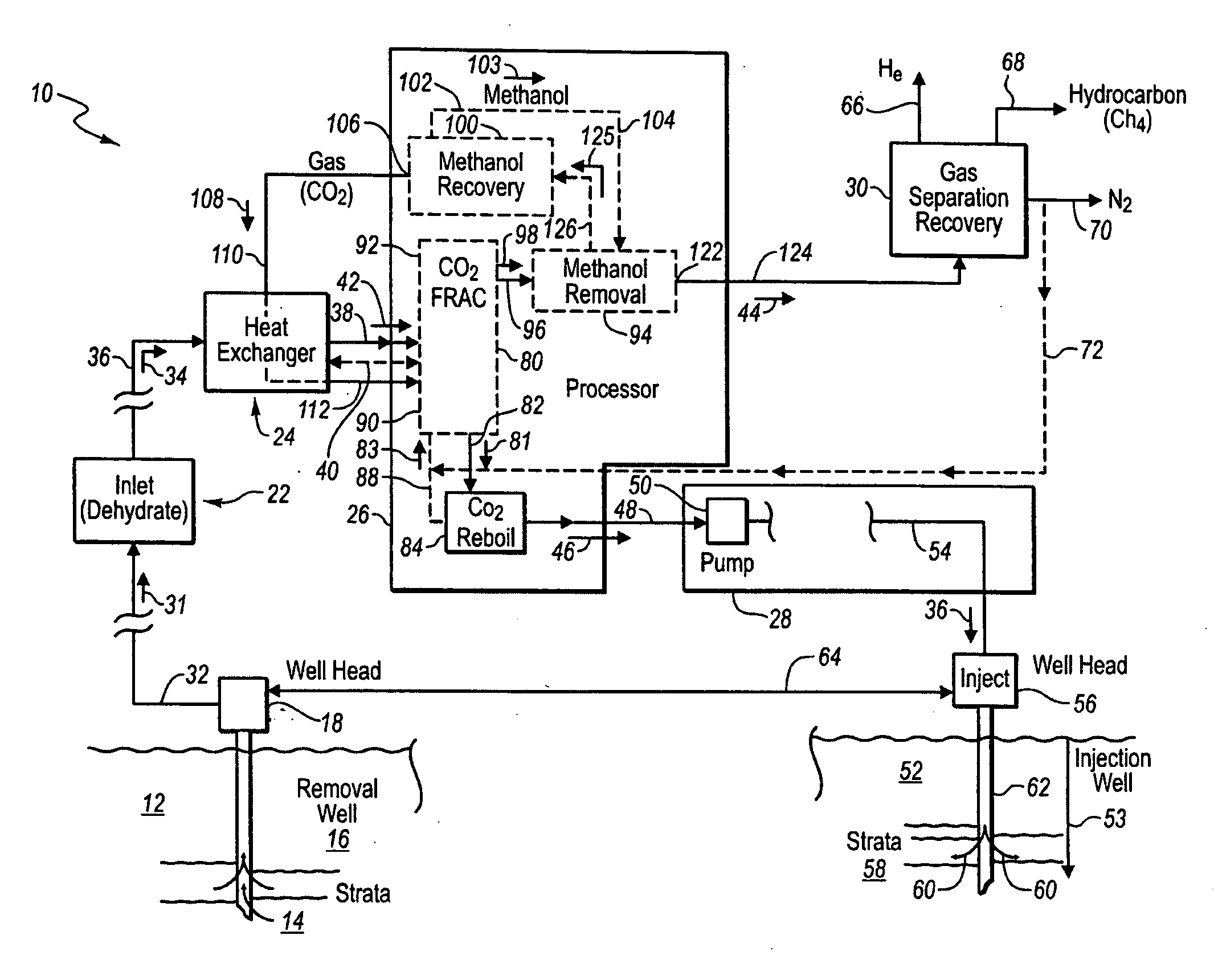
[0030]“Natural gas” means a gas that includes useable hydrocarbons like methane. It is recoverable from one or more ground wells or producing wells in a field the dimensions of which vary but which often involve many square miles of surface. The producing wells are positioned over a geological formation that contains the desired hydrocarbons. In fields of multiple wells, the producing wells are drilled into the gas producing underground geological formations and are spaced apart. Upon extraction at the wellhead, the produced gas is typically contaminated with water and water vapor along with some entrained particulates and even other fluids. In some cases, wellhead equipment removes entrained liquids and particulates. For example, filters and cyclone separators may be used proximate the wellhead to remove particulates and water from the produced gas and supply a relatively clean stream of produced gas to a suitable pipeline for delivery to a gas processing facility. The produced gas...


PUM

PropertyMeasurementUnit
distanceaaaaaaaaaa
distanceaaaaaaaaaa
temperatureaaaaaaaaaa

Abstract

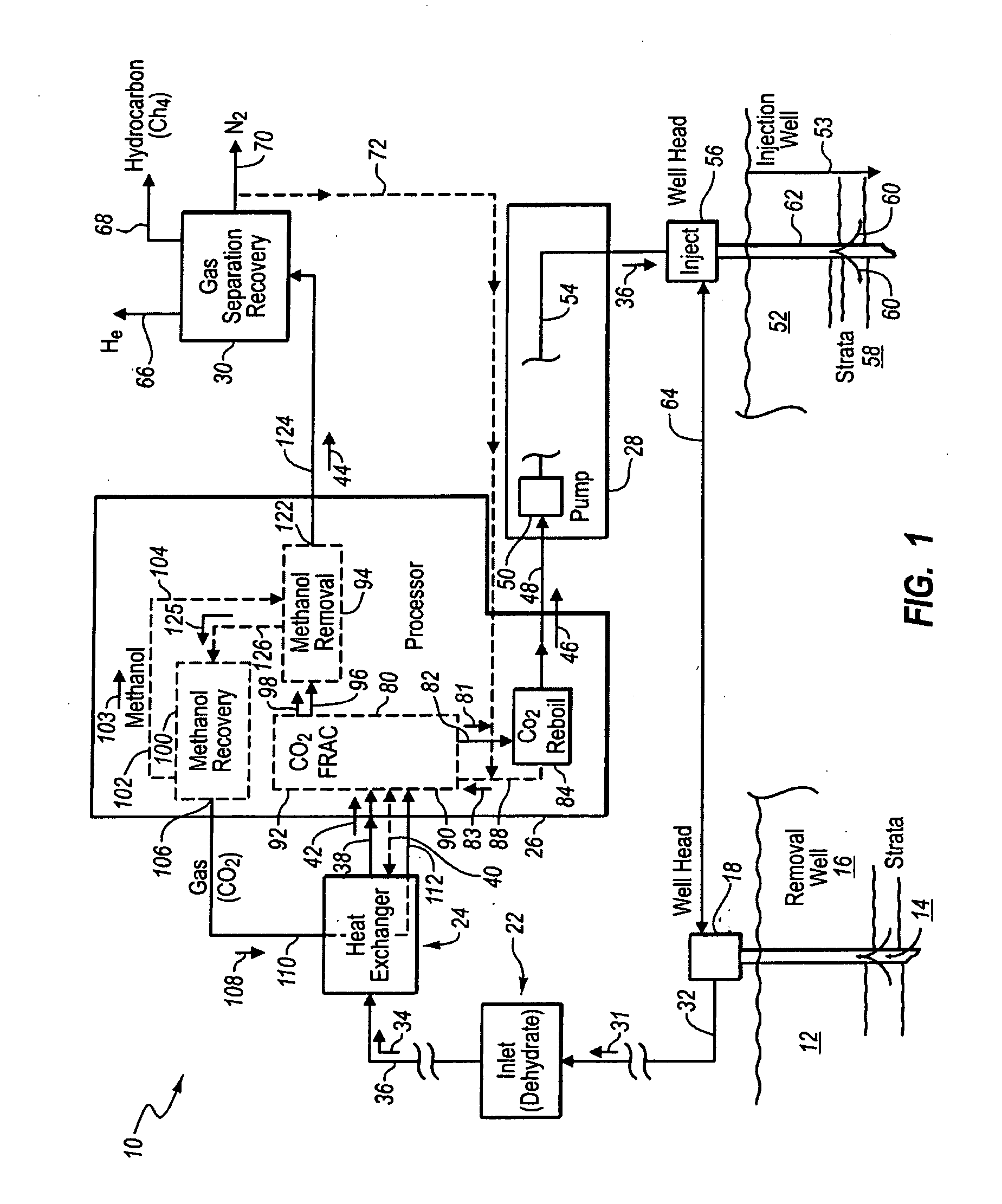
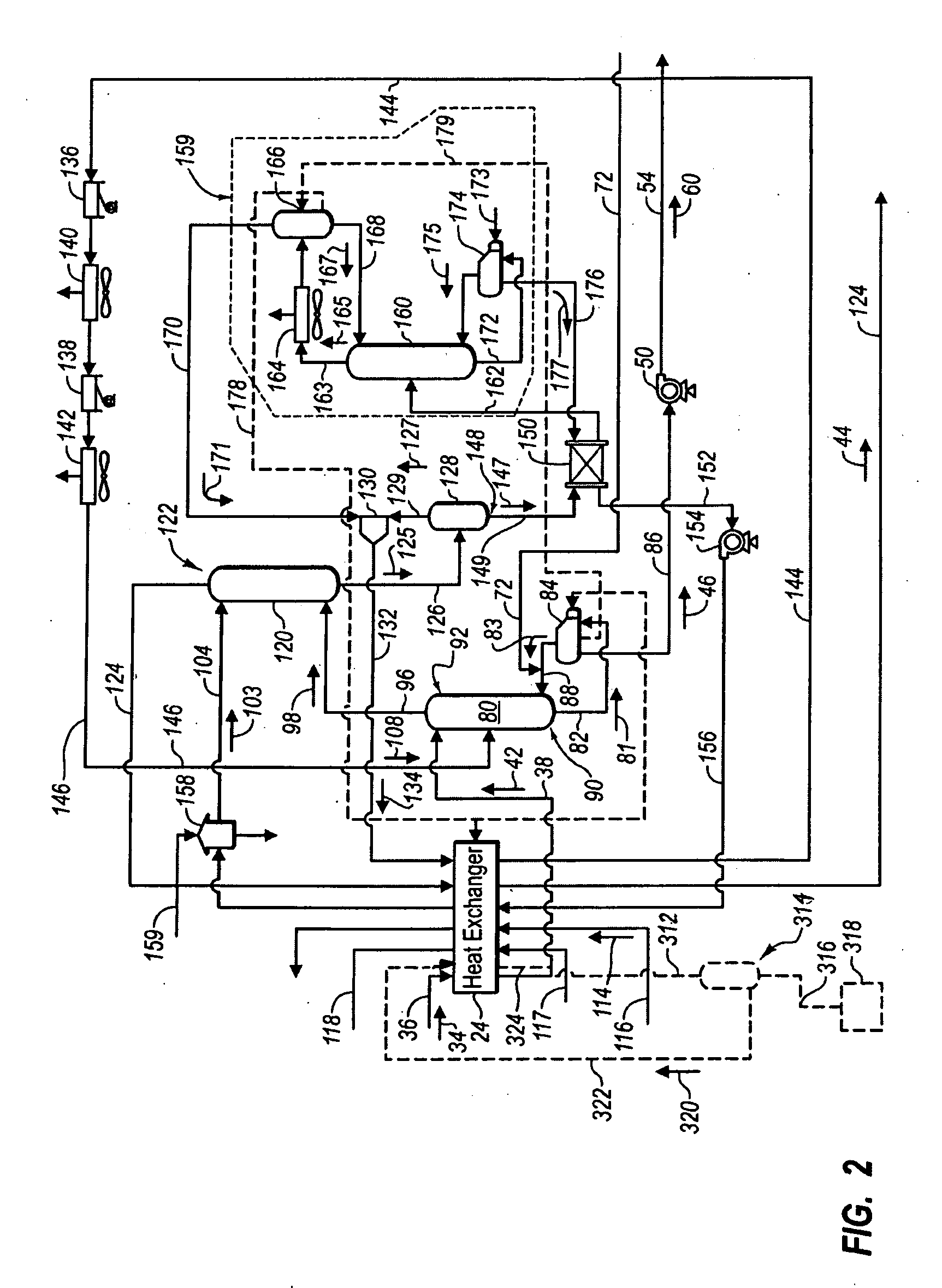
Produced natural gas containing carbon dioxide is dehydrated and chilled to liquefy the carbon dioxide and then fractionated to produce a waste stream of liquid carbon dioxide and hydrogen sulfide. Natural gas liquids may be first separated and removed before fractionation. After fractionation, the waste stream is pressurized and transmitted to a remote injection well for injection either for disposal of the waste stream and preferably to urge hydrocarbons toward the producing well. A hydrocarbon stream proceeds from fractionation to a methanol absorber system which removes carbon dioxide gas. The hydrocarbon stream is thereafter separated into at least hydrocarbon gas, nitrogen and helium. Some of the nitrogen is reintroduced into a fractionation tower to enhance the recovery of hydrocarbons. A methanol recovery system is provided to recover and reuse the methanol. The hydrocarbons are sold as natural gas and the helium is recovered and sold. Excess nitrogen is vented.

Description

PRIORITY CLAIM[0001]This divisional application claims the benefit of and priority from U.S. patent application Ser. No. 11 / 674,083 with a filing date of Feb. 12, 2007, which is hereby incorporated in its entirety and for all purposes by this reference.BACKGROUND OF THE INVENTION[0002]1. Field[0003]This invention relates to the processing of produced gases from a producing well and more particularly to processing the produced gases to concentrate the hydrocarbon gas and to separate hydrocarbon gas, other useable gases or liquids, certain unusable gases including waste gases, and to place the waste gases in a suitable form for injection into an injection well separate from the producing well.[0004]2. The Relevant Technology[0005]Natural gas is widely used today for home heating and cooking. As used herein, the term “natural gas” means a variety of hydrocarbon gases that are produced from a well (i.e., a producing gas well) drilled or bored into the ground or earth. Produced gas is ex...

Claims


Application Information

Patent Timeline
Patent Type & Authority Applications(United States)
IPC IPC(8): B01D53/78
CPCB01D53/002Y02C20/20B01D2256/24B01D2257/304B01D2257/504C10L3/10C10L3/102F25J3/0209F25J3/0233F25J3/0257F25J3/0266F25J3/029F25J2200/02F25J2200/30F25J2200/70F25J2200/74F25J2205/04F25J2245/42F25J2260/80F25J2290/40Y02C10/06Y02C10/08Y02C10/12B01D53/1418Y02C20/40
Inventor STINSON, DONALD LEO
Owner KATHY ANN STINSON NICHOLES IN HER REPRESENTATIVE CAPACITY AS TRUSTEE OF THE DONALD L STINSON 1994 TRUST U A DTD OCTOBER 24 1994 AS AMENDED
Learn More