
Nano-resonator including beam with composite structure

a composite structure and nano-resonator technology, applied in the direction of resonators, nanotechnology, semiconductor devices, etc., can solve the problems of difficult vapor deposition of sic, limited value of sic up to 30 nm, and the conventional nano-resonator has more problems at room temperature and atmospheric pressure, etc., to achieve easy operation, increase the electrical conductivity of the nano-beam, and increase the effect of favorability

Active Publication Date: 2008-12-04
SAMSUNG ELECTRONICS CO LTD
View PDF6 Cites 15 Cited by
  • Summary
  • Abstract
  • Description
  • Claims
  • Application Information

AI Technical Summary

Benefits of technology

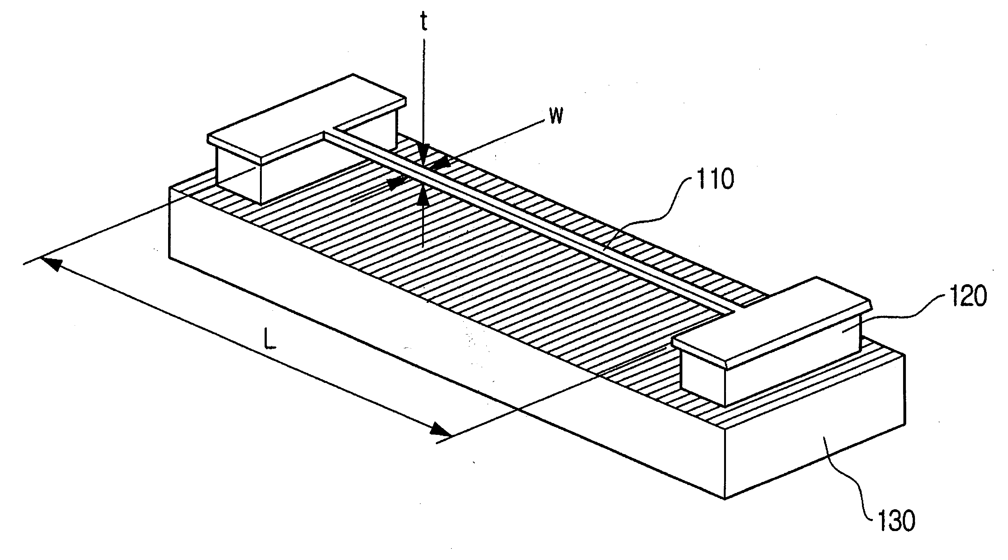
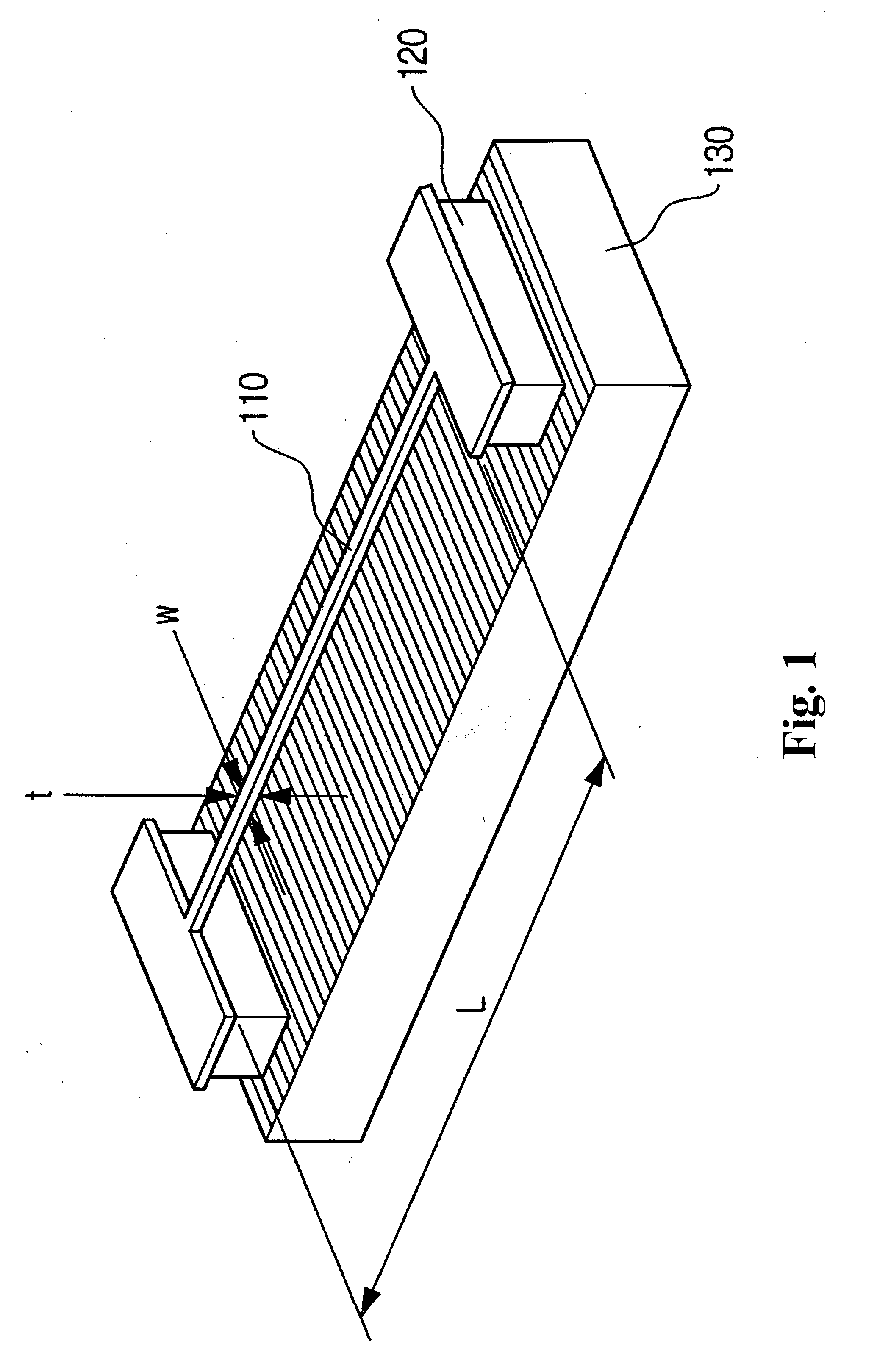
[0011]Example embodiments may provide a nano-resonator including a beam with a composite structure, which may increase an electrical conductivity of a nano-beam, need not require superconductive magnetic force lines, may sufficiently resonate even at a more moderate vacuum condition, may increase a favorability, and / or may more easily operate in a higher-frequency region of giga-hertz or more.

Problems solved by technology

However, a conventional nano-resonator has technical problems at room temperature and atmospheric pressure, and in a normal magnetic field, i.e., in non-superconductivity.
However, vapor deposition of SiC is more difficult, and a limitation value for SiC is up to 30 nm.
Therefore, the conventional nano-resonator may not be used at room temperature and atmospheric pressure or in a non-superconductive magnetic field.
The conventional nano-resonator is more difficult to operate in the higher-frequency region of giga-hertz (GHz) or more.

Method used


Image

  • Nano-resonator including beam with composite structure
  • Nano-resonator including beam with composite structure
  • Nano-resonator including beam with composite structure

Examples


Embodiment Construction

[0022]Example embodiments will now be described more fully hereinafter with reference to the accompanying drawings. Embodiments may, however, be in many different forms and should not be construed as being limited to the example embodiments set forth herein. Rather, these example embodiments are provided so that this disclosure will be thorough and complete, and will fully convey the scope to those skilled in the art. In the drawings, the thicknesses of layers and regions may be exaggerated for clarity.

[0023]It will be understood that when a component is referred to as being “on,”“connected to” or “coupled to” another component, it can be directly on, connected to or coupled to the other component or intervening components may be present. In contrast, when a component is referred to as being “directly on,”“directly connected to” or “directly coupled to” another component, there are no intervening components present. As used herein, the term “and / or” includes any and all combinations...


PUM

PropertyMeasurementUnit
pressureaaaaaaaaaa
aspect ratioaaaaaaaaaa
magnetic fieldaaaaaaaaaa

Abstract

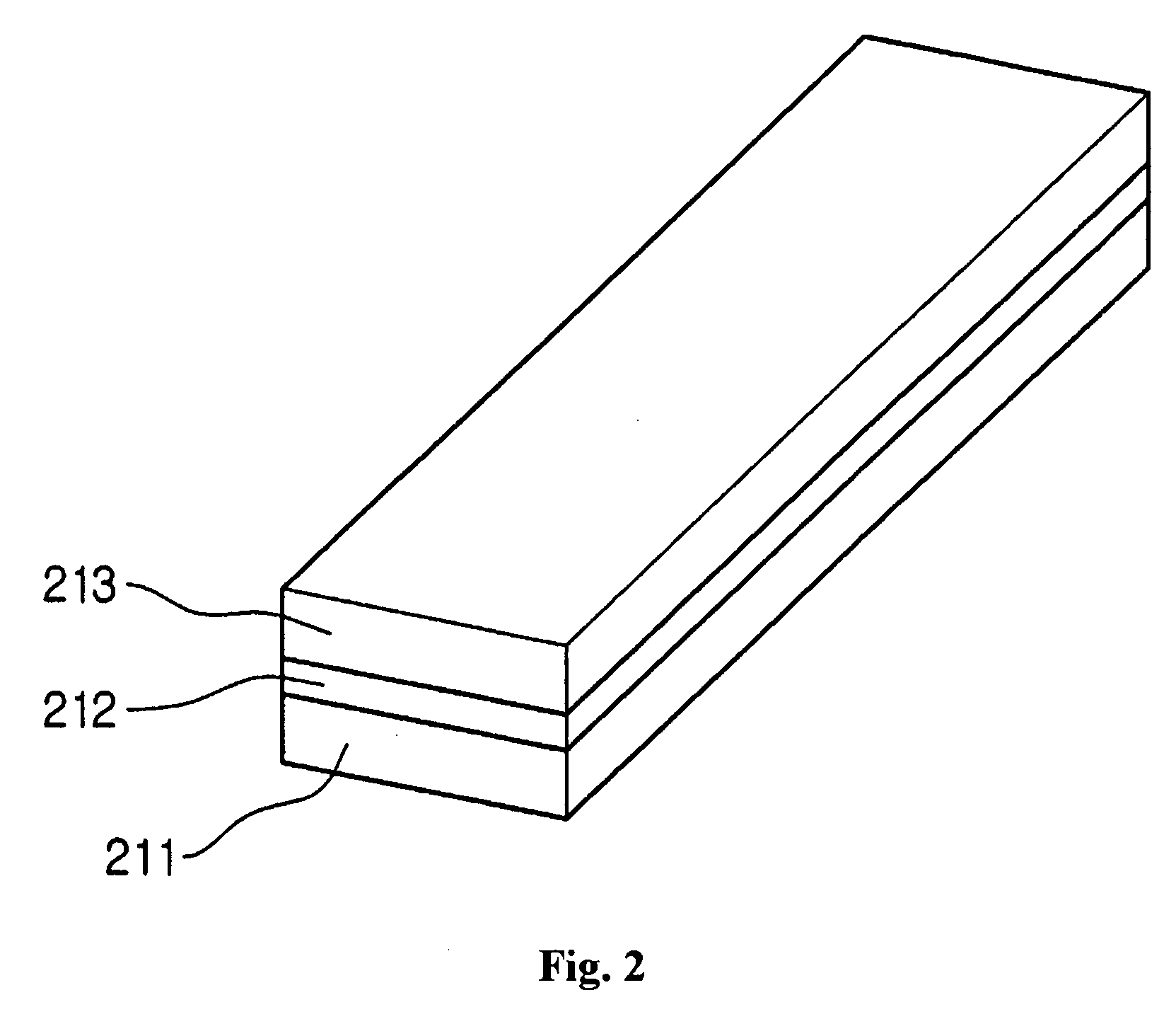
A nano-resonator including a beam having a composite structure may include a silicon carbide beam and / or a metal conductor. The metal conductor may be vapor-deposited on the silicon carbide beam. The metal conductor may have a density lower than a density of the silicon carbide beam.

Description

PRIORITY STATEMENT[0001]This application claims the benefit of priority to Korean Patent Application No. 10-2007-0053705, filed on Jun. 1, 2007, in the Korean Intellectual Property Office, the entire contents of which are incorporated herein in their entirety by reference.BACKGROUND[0002]1. Field[0003]Example embodiments relate to a nano electromechanical system, and for example, to a nano-resonator including a beam with a composite structure.[0004]2. Description of Related Art[0005]A conventional micro electromechanical system (MEMS) includes a sensor for detecting various physical or chemical properties. As a dimension of a mechanical transducer is reduced, a new generation system having improved sensitivity, spatial resolution, energy efficiency, and reaction time, which is referred to as a nano electromechanical system (NEMS), has been developed.[0006]For an apparatus in the communications field, a higher favorability, i.e., a higher Q (quality factor) value, is desired, so that...

Claims


Application Information

Patent Timeline
Patent Type & Authority Applications(United States)
IPC IPC(8): H03H9/00
CPCB82Y15/00H03H9/02244H03H9/2463Y10S977/932Y10S977/712Y10S977/724Y10S977/72H01P7/00
Inventor JUN, SEONG CHANKIM, SUN ILBAIK, CHAN WOOK
Owner SAMSUNG ELECTRONICS CO LTD
Learn More