Radio communication system

a radio communication system and radio communication technology, applied in the field of radio communication devices, can solve the problems of not allowing for any reradiation of received signals, and achieve the effects of reducing coupling between antennas, and maintaining signal strength

Active Publication Date: 2008-11-27
HELIX TECH
View PDF38 Cites 13 Cited by
  • Summary
  • Abstract
  • Description
  • Claims
  • Application Information

AI Technical Summary

Benefits of technology

[0023]These equations demonstrate how coupling between antennas reduces the capacity of the MIMO channel.
[0025]Polarisation and pattern diversity are achieved by using receive antennas with differently oriented radiation patterns which are sensitive to differently polarised signals. Theoretically, polarisation diversity results in high statistically independence between signals generated by adjacent antennas. However, in practice, when antennas are placed close together to the extent that their near-field regions overlap, the radiation patterns combine, and polarisation and pattern diversity is significantly reduced. The statistical independence between signals fed from adjacent antennas is therefore also reduced.
[0029]With such an antenna, the electromagnetic near-field can be concentrated within the dielectric core of the antenna. This results in a significant reduction in the extent and strength of the near-field adjacent such an antenna when compared with, for example, the near-field associated with a monopole antenna. It is possible, therefore, for a given antenna spacing, significantly to reduce the coupling between adjacent antennas and, therefore, to reduce the correlation between signals obtained from the antennas.
[0033]The first maximum may lie substantially in a first plane and the said second maximum substantially in a second plane, the first plane being orthogonal to the second plane. Each of said antennas may be oriented within the device such that its associated first plane, is orthogonal to a first plane of an adjacent antenna. This provides polarisation diversity and takes advantage of the polarisation scattering caused by a typical multipath environment. Such an arrangement also contributes to maintaining signal strength with different orientations of a portable terminal in accordance with the invention.
[0034]Preferably, each antenna is configured such that, at an operational frequency of the antennas, with respect to a signal received at that frequency, each antenna has a null in its radiation pattern. The device may then be arranged such that at least one of the antennas is oriented to direct its null towards another of the receive antennas. This also reduces coupling between the antennas, i.e. by configuring the antennas to have nulls in the radiation patterns at the operating frequencies of the antennas and orientating them appropriately. The near-field is, therefore, reduced in the direction of other antennas thereby reducing coupling between the antennas.
[0039]There may be an isolating trap associated with each antenna so that it is isolated from the ground plane of the radio communication device. This arrangement minimises any direct coupling between the antennas through the ground plane. This reduces correlation between signals from neighbouring antennas. Generally, the trap is in the form of a balun, located between the antenna element structure of the antenna and the radio-frequency (RF) circuitry of the radio communication device to which it is coupled. In the case of the antenna having a plurality of elongate antenna conductors coupled to a feed structure and forming part of a loop, the trap may comprise a link conductor. This link conductor may be a conductive sleeve encircling the core on a proximal part of the outer surface of the core, the proximal end of the sleeve being connected to an outer screen part of the feeder structure, the latter passing through the core from a connection to the antenna elements at a distal end of the core, to a proximate end of the core. An effect of the sleeve is that, at the operating frequency of the antenna, a rim of the sleeve is effectively isolated from the ground represented by the outer conductor of the feeder structure at the proximal end. The sleeve therefore acts as an isolating trap in the manner described in GB-A-2292638 and GB-A-2309592, the contents of which are hereby incorporated by reference.

Problems solved by technology

This model does not account for any reradiation of received signals between receive antennas.

Method used


Image

  • Radio communication system
  • Radio communication system
  • Radio communication system

Examples


Embodiment Construction

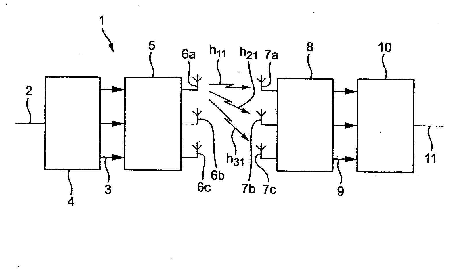
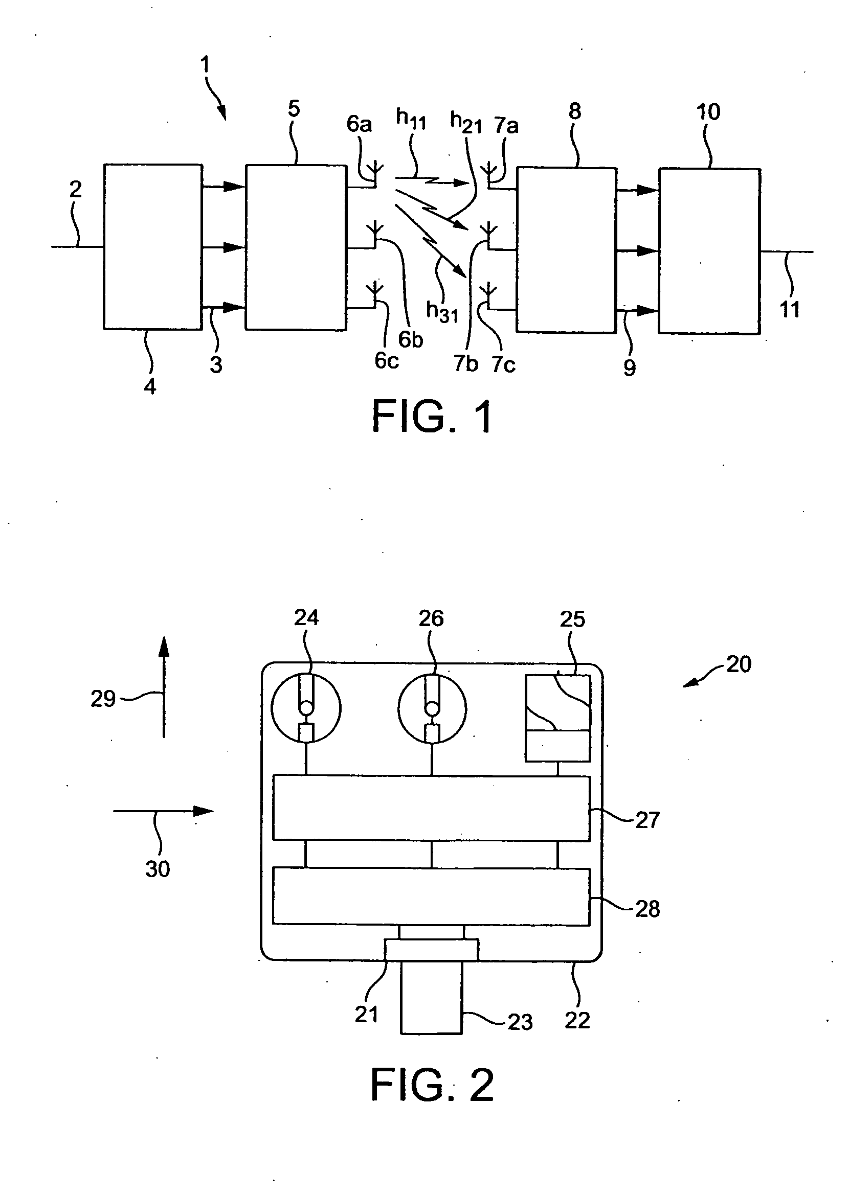
[0058]Referring to FIG. 1, in a MIMO radio communications system 1 a data stream 2 is split at the transmit end into a number of orthogonally coded sub-streams 3 by transmitter signal processor 4. The sub-streams are then transmitted by a transmitter 5 via respective transmit antennas 6a, 6b and 6c. At the receive end, each receive antenna 7a, 7b and 7c receives all of the signals transmitted by the transmit antennas. In addition, each receive antenna receives any reflected versions of the individual sub-streams, caused by objects in the environment such as buildings. The receive antennas are coupled to a receiver 8, from which received sub-streams 9 are passed to a receiver signal processor 10. The receiver signal processor combines the received sub-streams to produce reconstituted data stream 11. This includes a data multiplexing process. The MIMO channel that exists in a given scattering environment, may be represented by the channel matrix [H]. This matrix is characterised by tr...


PUM

PropertyMeasurementUnit
Timeaaaaaaaaaa
Frequencyaaaaaaaaaa
Frequencyaaaaaaaaaa

Abstract

A radio communication receiver which includes an antenna array having at least two antennas to provide antenna diversity. The receiver is for receiving signals containing orthogonally coded data sub-streams derived from a source data stream. The receiver also has receiver circuitry, coupled to the antenna array, having a detection stage to detect the data sub-streams and a combiner stage for combining the detected data sub-streams to recover the source data stream. Each antenna has an electrically insulative core of solid material having a dielectric constant greater than 5. Each antenna also has a three-dimensional antenna element structure disposed on or adjacent the outer surface of the core.

Description

CROSS-REFERENCES TO RELATED APPLICATIONS[0001]This application claims a benefit of priority under 35 U.S.C. 119(e) from copending provisional patent application U.S. Ser. No. 60 / 921,768, filed Apr. 3, 2007, the entire contents of which are hereby expressly incorporated herein by reference for all purposes. This application is related to, and claims a benefit of priority under one or more of 35 U.S.C. 119(a)-119(d) from copending foreign patent application 0624973.4, filed in the United Kingdom on Dec. 14, 2006 under the Paris Convention, the entire contents of which are hereby expressly incorporated herein by reference for all purposes.BACKGROUND INFORMATION[0002]1. Field of the Invention[0003]The present invention relates to a radio communication device and, in particular, radio communication devices for use in a multi-channel radio communication system.[0004]2. Discussion of the Related Art[0005]In the field of radio communications, multiple-input multiple-output (MIMO) systems tr...

Claims


Application Information

Patent Timeline
IPC IPC(8): H04J11/00G03C1/74B29C33/00B29C33/02B29C43/00B29C59/00B29C59/04B29C65/00B29C67/00B29C71/00B29D1/00
CPCB29C33/026B29C59/04B29C66/8248H01Q1/242H01Q11/08H01Q21/24H01Q21/28H04B7/0697H04B7/0837H01Q1/52H04B7/04H04L1/02H01Q1/362
Inventor LEISTEN, OLIVER PAUL
Owner HELIX TECH
Why Eureka
Try Eureka