
Compact diversity antenna arrangement

a technology of compact antennas and antennas, applied in the structure of radiating elements, independent non-interacting antenna combinations, resonance antennas, etc., can solve the problems of difficult to provide diversity solutions in portable communication devices, small portable communication devices such as cellular phones, and difficult to implement at portable communication devices

Inactive Publication Date: 2008-11-27
SONY ERICSSON MOBILE COMM AB
View PDF10 Cites 2 Cited by
  • Summary
  • Abstract
  • Description
  • Claims
  • Application Information

AI Technical Summary

Benefits of technology

[0005]The present invention is generally directed towards providing an antenna arrangement that is small, can be provided inside a portable communication device and provides diversity.
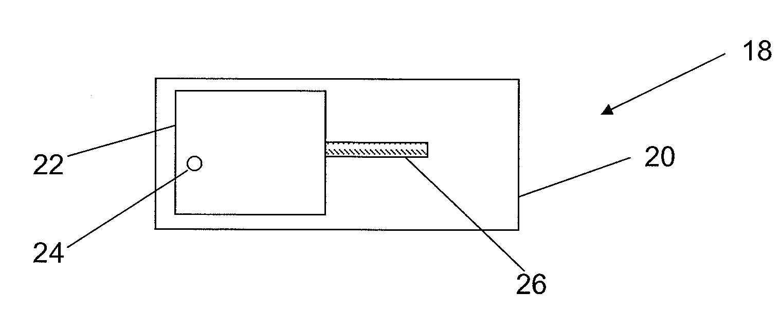
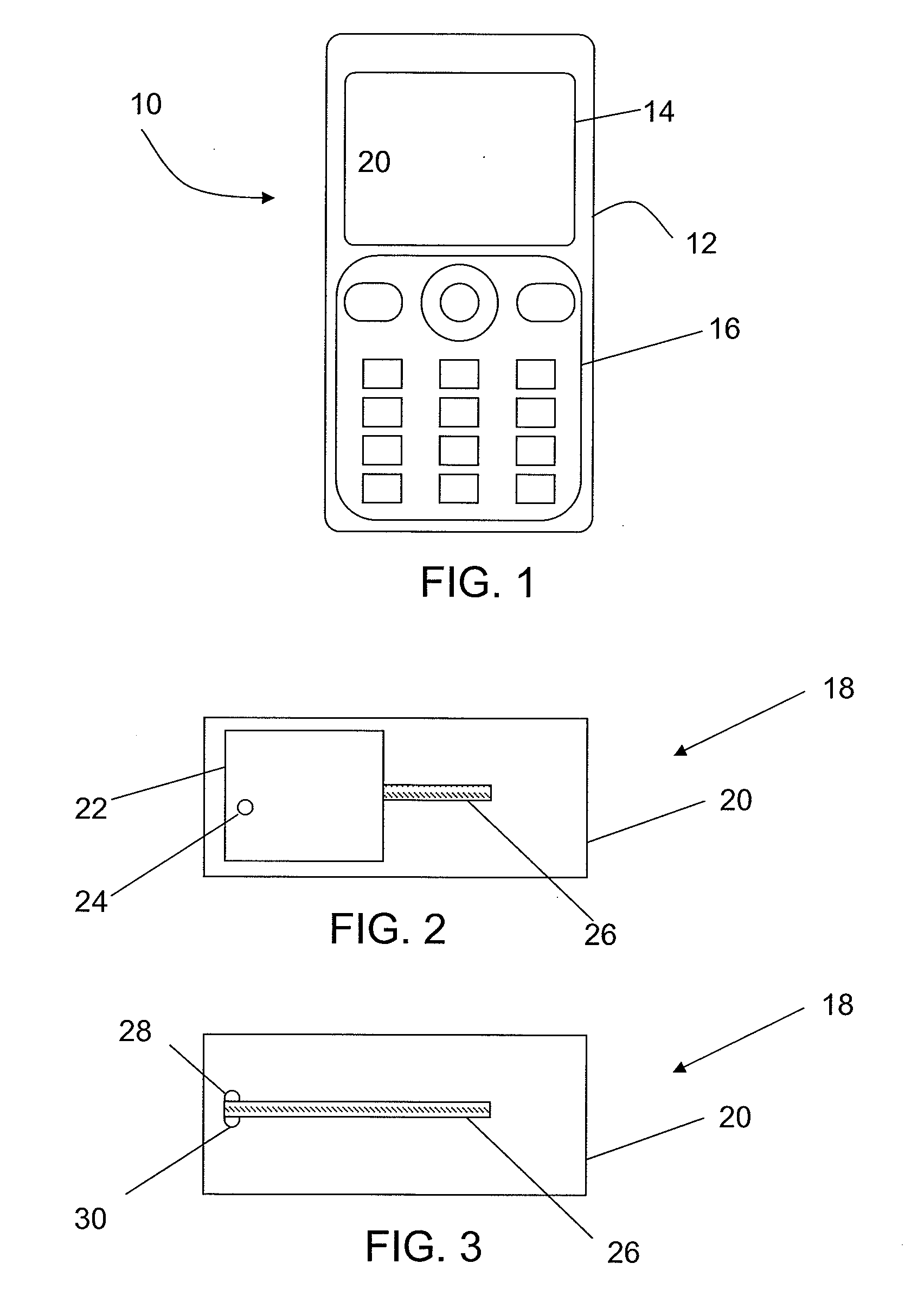
[0034]The invention has a number of advantages. By providing a first radiating electric antenna element on top of a second radiating magnetic antenna element in a ground plane, the magnetic field of the second radiating magnetic antenna element is aligned with the electric field of the first radiating electric antenna element, and the electric field of the second radiating magnetic antenna element is aligned with the magnetic field of the first radiating electric antenna element. This improves the isolation between the radiating antenna elements even though they are provided in the same area. The antenna arrangement is furthermore provided in a small area which is normally already provided for a single antenna and thus the antenna diversity can be obtained with virtually no additional space. It is further simple and can be produced at a low cost.

Problems solved by technology

This is however hard to implement at a portable communication device for the size of devices that are near or less than the wavelength of the radio-channel in use and this is the case for cellular phone handsets operating in the 800 to 2000 MHz bands.
Portable communication devices like cellular phones are thus very small.
This means that it is very difficult to provide a diversity solution in a portable communication device that has an acceptable isolation.
The devices are thus often not large enough to obtain acceptable isolation.
If an additional antenna element is provided, this will then also occupy additional space in the device, which may be very hard to provide because of the many other elements that it is desirable to provide in a small sized portable communication device.

Method used


Image

  • Compact diversity antenna arrangement
  • Compact diversity antenna arrangement
  • Compact diversity antenna arrangement

Examples


second embodiment

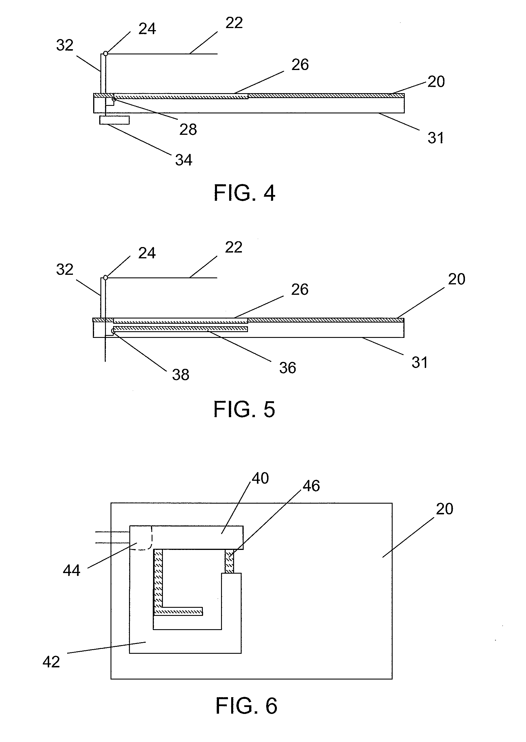
[0050]The slot used can be a cavity backed slot. An example of a second embodiment using such a solution is shown in FIG. 5, which shows a sectional view of an antenna arrangement 18 on a substrate 31. Here there is provided a cavity 36 in the substrate 31 underneath the slot 26. The slot 26 is here capacitively fed by the cavity 36. Thus here the connection points 38 for the slot 26 (of which only one is shown) are provided to the cavity 36 and not directly to the slot 26.

[0051]It is possible to apply the concept of the present invention also on multi-resonating antenna elements. One such example according to a third embodiment of the present invention is shown in FIGS. 6 and 7, which shows a multi resonating antenna arrangement 18 with a PIFA element (FIG. 6) and without the PIFA element (FIG. 7) in views that are similar to the views of FIGS. 2 and 3. Here the PIFA element includes a feeding section 44 with connections to ground and the radio circuit. The feeding section 44 is al...

third embodiment

[0053]A plot of the VSWR 52 (Voltage Standing Wave Ratio) and isolation 54 (expressed in dB) of an antenna arrangement according to the principles of the third embodiment for a frequency range of 0.5-3 GHz is shown in a curve in FIG. 8. As can be seen the antenna arrangement provides good characteristics for a wide frequency range covering the two resonance frequencies and the bands they are provided in, i.e. covering the 850 and 1800 MHZ bands and also has good isolation in this range, which enables the use of the antenna for diversity applications.

[0054]It should here be realised that it is also possible to add a third radiation antenna element, which may be another slot antenna. This may be done through bending a part of the ground plane so that the ground plane has two sections, a first which is provided under the first radiating antenna element and being parallel with the plane in which this first radiating antenna element is provided. The second radiating antenna element is he...


PUM


Abstract

The present invention relates to an antenna arrangement for a portable communication device as well as to a portable communication device comprising such an antenna arrangement. The antenna arrangement includes a ground plane, a first radiating electrical antenna element provided in a plane arranged at a distance above and parallel with at least a part of the ground plane, where the first radiating electrical antenna element is dimensioned for resonating at least at one frequency, and a second radiating magnetic antenna element provided in the ground plane below the first antenna element and being dimensioned for resonating at the same frequency as the first radiating antenna element.

Description

TECHNICAL FIELD OF THE INVENTION[0001]The present invention relates to providing antenna diversity in wireless communication and more particularly to an antenna arrangement for a portable communication device as well as to a portable communication device having such an antenna arrangement.DESCRIPTION OF RELATED ART[0002]Mobile communication at high data rates, such as HSPA (High Speed Packet Access), demands the introduction of advanced radio communication link systems or equipment that better to the nature of radio wave propagation properties of wireless channels than communication at lower rates. One way to solve this is to introduce two or more antennas at either or both of the receiver and transmitter ends of a communication network. Antennas applied for these types of solutions are often termed diversity antennas, MIMO (Multiple Input Multiple Output) or MISO (Multiple Input Single Output) antennas. The configuration of such antennas has to offer some degree of independence, i....

Claims


Application Information

Patent Timeline
Patent Type & Authority Applications(United States)
IPC IPC(8): H01Q9/04H01Q13/10H01Q9/16
CPCH01Q1/243H01Q9/0421H01Q13/10H01Q21/28
Inventor BOLIN, THOMAS
Owner SONY ERICSSON MOBILE COMM AB
Learn More