Ultrasonic flow sensor

a technology of ultrasonic flow and sensor, which is applied in the direction of volume/mass flow measurement, measurement devices, instruments, etc., can solve the problems of reducing the measurement accuracy and reliability, affecting the accuracy and reliability of measurement, and the ownership of ultrasonic flow sensors, so as to reduce the flow transition point, accurate and reliable measurement of average velocity, and low cost of ownership

Inactive Publication Date: 2013-07-18
SPIRE METERING TECH
View PDF2 Cites 13 Cited by
  • Summary
  • Abstract
  • Description
  • Claims
  • Application Information

AI Technical Summary

Benefits of technology

The present invention is an ultrasonic flow sensor that can accurately and reliably measure the average velocity of liquid and gaseous media. It has a structure that reduces flow transition points and suppresses parasitic multi-mode waves, resulting in higher measurement accuracy and reliability. It employs a pair of ultrasound wave reflecting mirrors with flat or convex top surface to prevent particle deposition onto the mirror surface. It uses hemispheres or hemi-elliptical spheres as the reflecting mirror holders to improve the flow velocity uniformity along the measuring path. The sensor provides a mechanism to set the reflecting mirrors to the position and orientation in such a way that their disturbance to the flow to be measured is minimized while the ultrasonic signal strength is maintained. Its simple and unique structure makes it easy to assemble and easy to manufacture.

Problems solved by technology

On the other hand, the parasitic multi-mode ultrasonic wave generated by the internal reflection has negative impact on measurement accuracy and reliability.
The stronger the parasitic multi-mode ultrasonic wave, the lower the measurement accuracy and reliability.
The cost of ownership of ultrasonic flow sensors depends on the initial product price and its life cycle.

Method used


Image

  • Ultrasonic flow sensor
  • Ultrasonic flow sensor
  • Ultrasonic flow sensor

Examples


Embodiment Construction

[0036]The following description is merely exemplary in nature and is not intended to limit the present disclosure, application, or uses. It should be understood that throughout the drawings, corresponding reference numerals indicate like or corresponding parts and features.

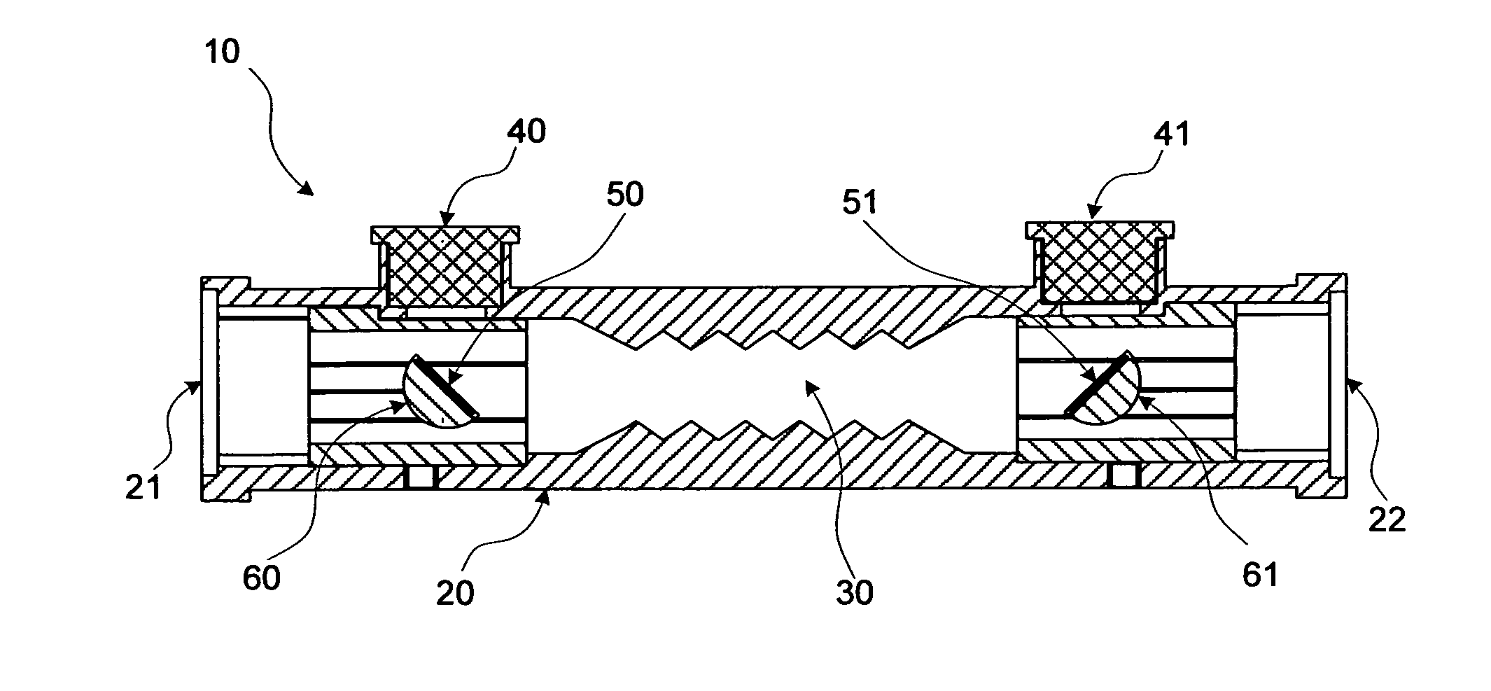
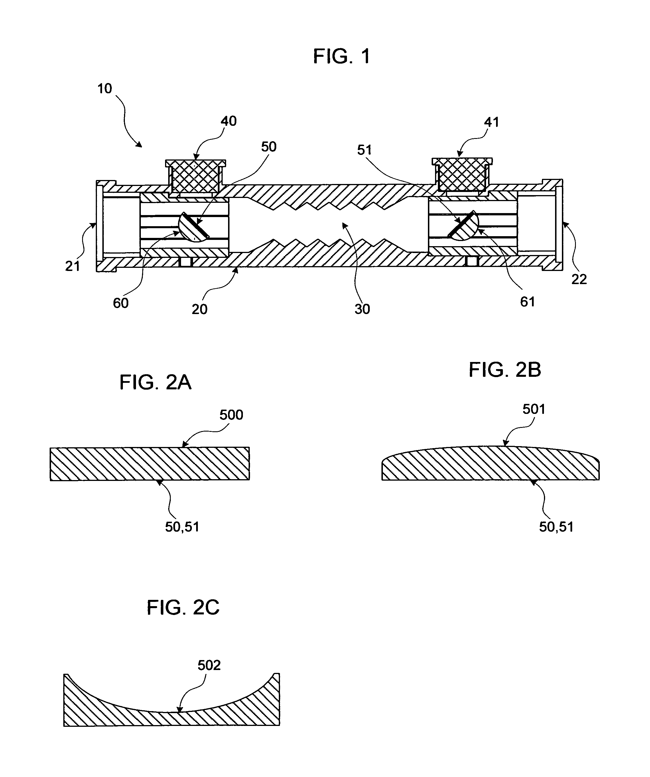
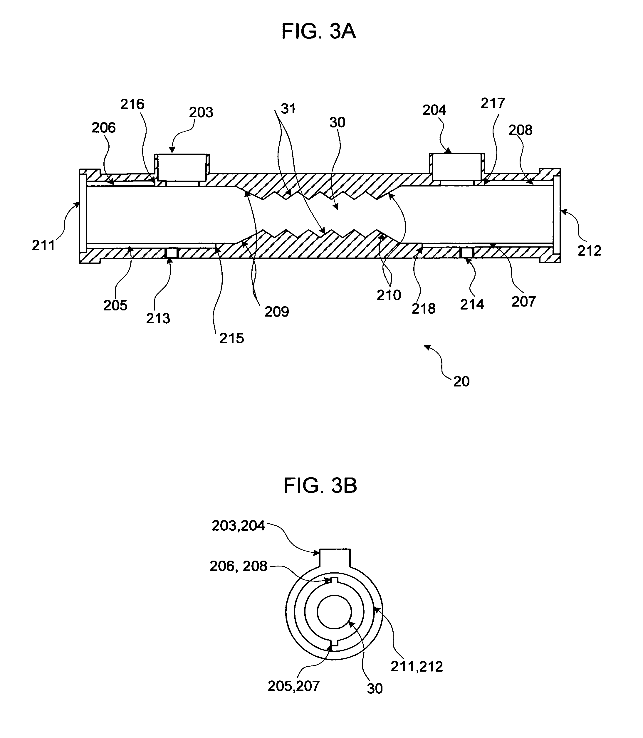
[0037]Referring to FIG. 1, an ultrasonic flow sensor 10 consists of a flow cell body 20 with an inlet 21 on one side and an outlet 22 on the other side through which the liquid or gaseous media flows, an inner flow conduit 30 with a rough surface which not only decreases the flow transition point from turbulence regime to laminar regime but also suppresses the parasitic multi-mode ultrasonic waves, one pair of electro-ultrasonic transducers 40, 41 for transmitting and receiving ultrasound signals, one pair of ultrasonic wave reflecting mirrors 50, 51 for guiding the ultrasonic waves from one transducer to the other, and one pair of reflecting mirror support fixtures 60 and 61 which align the reflecting mirrors to ...


PUM


Abstract

An ultrasonic flow sensor comprises a flow cell body with an inlet on one side and an outlet on the other side through which the liquid or gaseous media flows; an inner flow conduit with rough surface which not only decreases the flow transition point from turbulence regime to laminar regime but also suppresses the parasitic multi-mode ultrasonic waves; one pair of electro-ultrasonic transducers for transmitting and receiving ultrasound signals; one pair of ultrasonic wave reflecting mirrors for guiding ultrasonic waves from one transducer to the other; and two reflecting mirror support fixtures which set the position and orientation of the ultrasonic wave reflecting mirrors in such a way that their disturbance to the flow inside the inner flow conduit is minimized while the ultrasonic signal strength is maintained.

Description

CROSS-REFERENCE TO RELATED APPLICATIONS[0001]Not Applicable.STATEMENT REGARDING FEDERALLY SPONSORED RESEARCH OR DEVELOPMENT[0002]Not Applicable.[0003]REFERENCE TO SEQUENCE LISTING, A TABLE, OR A COMPUTER PROGRAM LISTING COMPACT DISC APPENDIX[0004]Not Applicable.FIELD OF THE INVENTION[0005]The present disclosure relates to an ultrasonic flow sensor for measuring the average velocity of liquid and gaseous media.BACKGROUND OF THE INVENTION[0006]The statements in this section merely provide background information related to the present disclosure and may not constitute prior art.[0007]An ultrasonic flow sensor measures the average velocity of liquid or gaseous media by means of ultrasonic transducers based on the principle that the transit time of an ultrasonic wave from the transmitter of a transducer to the corresponding receiver is determined by the fluid velocity and the ultrasonic wave propagating direction. Normally, a pair of transducers is used, one is installed in upstream and ...

Claims


Application Information

Patent Timeline
Patent Type & Authority Applications(United States)
IPC IPC(8): G01F1/66
CPCG01F1/662G10K11/28
Inventor SHEN, CHANG
Owner SPIRE METERING TECH
Why Eureka
Try Eureka