
Wide angle mirror system

a mirror system and wide angle technology, applied in the field of mirror systems, can solve the problems of reducing system reflectivity, absorbing light, and insufficient reflection of light at wavelengths of interest, and achieve the effect of high reflectivity of the mirror system

Inactive Publication Date: 2008-11-27
3M INNOVATIVE PROPERTIES CO
View PDF14 Cites 21 Cited by
  • Summary
  • Abstract
  • Description
  • Claims
  • Application Information

AI Technical Summary

Benefits of technology

The solution provides high reflectivity for both normally incident and extreme angle light, maintaining uniformity despite localized backside disturbances, and extends the reflection band into the near-infrared for visible light uniformity.

Problems solved by technology

On the other hand, if the backside is scratched or in contact with an absorbing material (e.g. a support member, fastener, grease, ink, or dirt), such light is absorbed, detracting from system reflectivity.
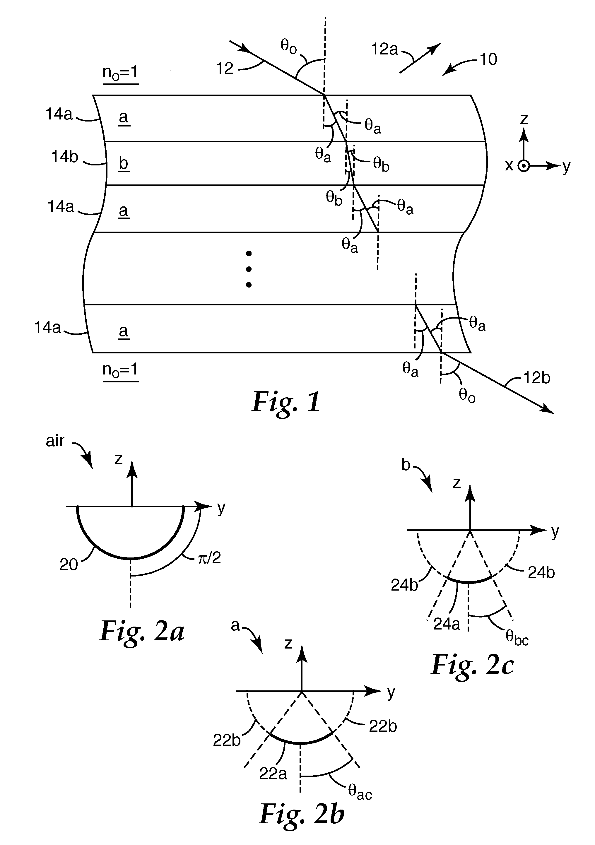
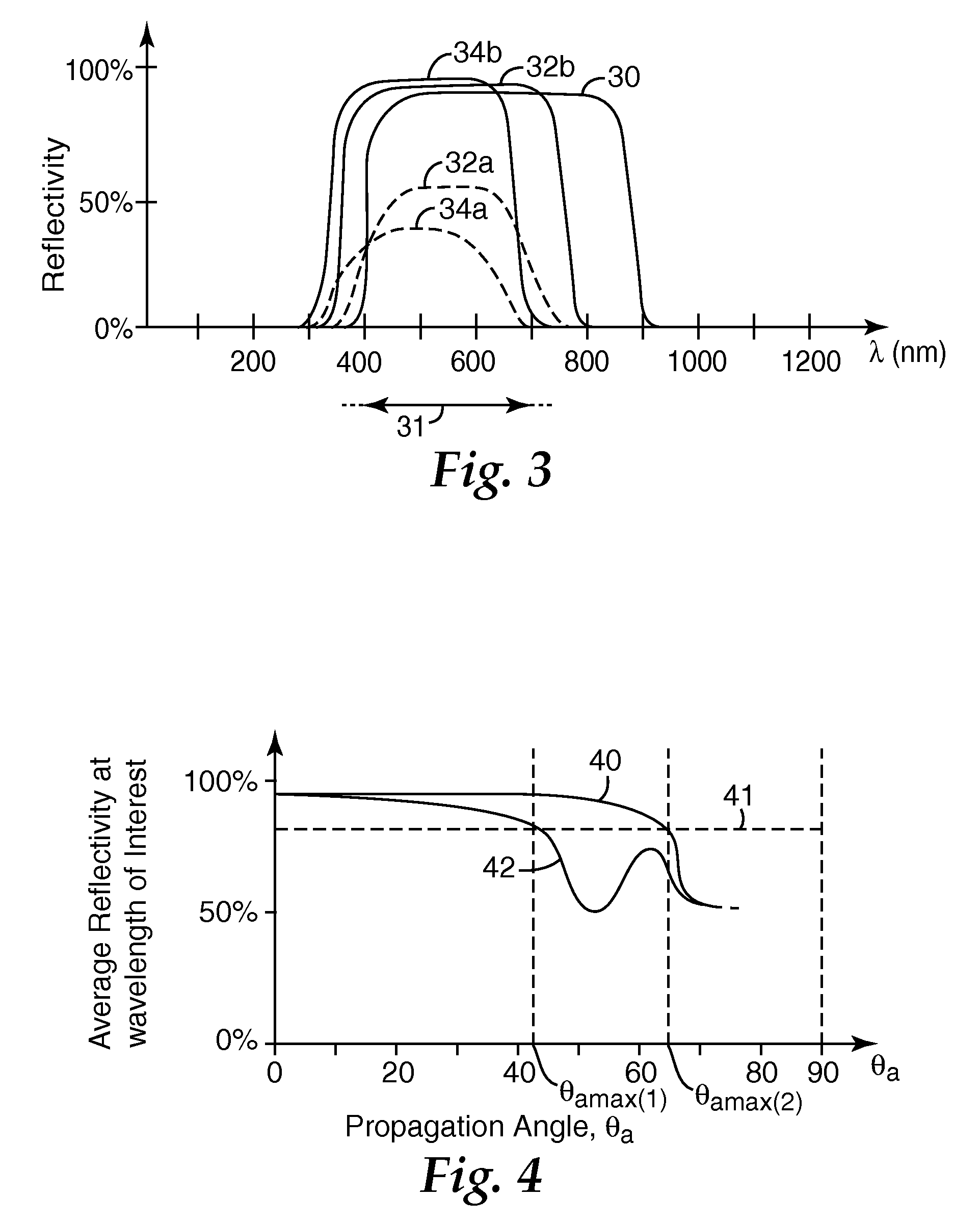
The diffusing elements cause some of the scattered light to enter the mirror at sufficiently high angles of incidence so that the light is not adequately reflected at wavelengths of interest (for example, due to a shift in the mirror reflection band at high angles of incidence).

Method used


Image

  • Wide angle mirror system
  • Wide angle mirror system
  • Wide angle mirror system

Examples


example 1

[0070]An extended band mirror film stack was made by using an optical adhesive to laminate together two multilayer mirrors made from oriented PEN and PMMA. The first mirror was made with 530 layers of PEN / PMMA formed using a multiplier and two packets of 265 layers each according to the methods described in U.S. Pat. No. 6,783,349 (Neavin et al.) to provide a visible and near-infrared mirror with a reflectance band, for normally incident unpolarized light, extending from about 400 nm to about 1000 nm. The second mirror was similarly made but contained only one packet of 265 layers of PEN / PMMA to provide an infrared mirror with a reflectance band from about 1000 nm to 1700 nm. Each mirror was biaxially stretched under suitable conditions to render the PEN material birefringent, with substantially equal in-plane refractive indices (measured at 633 nm) of about 1.75 and a z-axis refractive index of about 1.49, while the PMMA material remained substantially isotropic with a refractive i...


PUM

PropertyMeasurementUnit
wavelength rangeaaaaaaaaaa
angleaaaaaaaaaa
propagation angleaaaaaaaaaa

Abstract

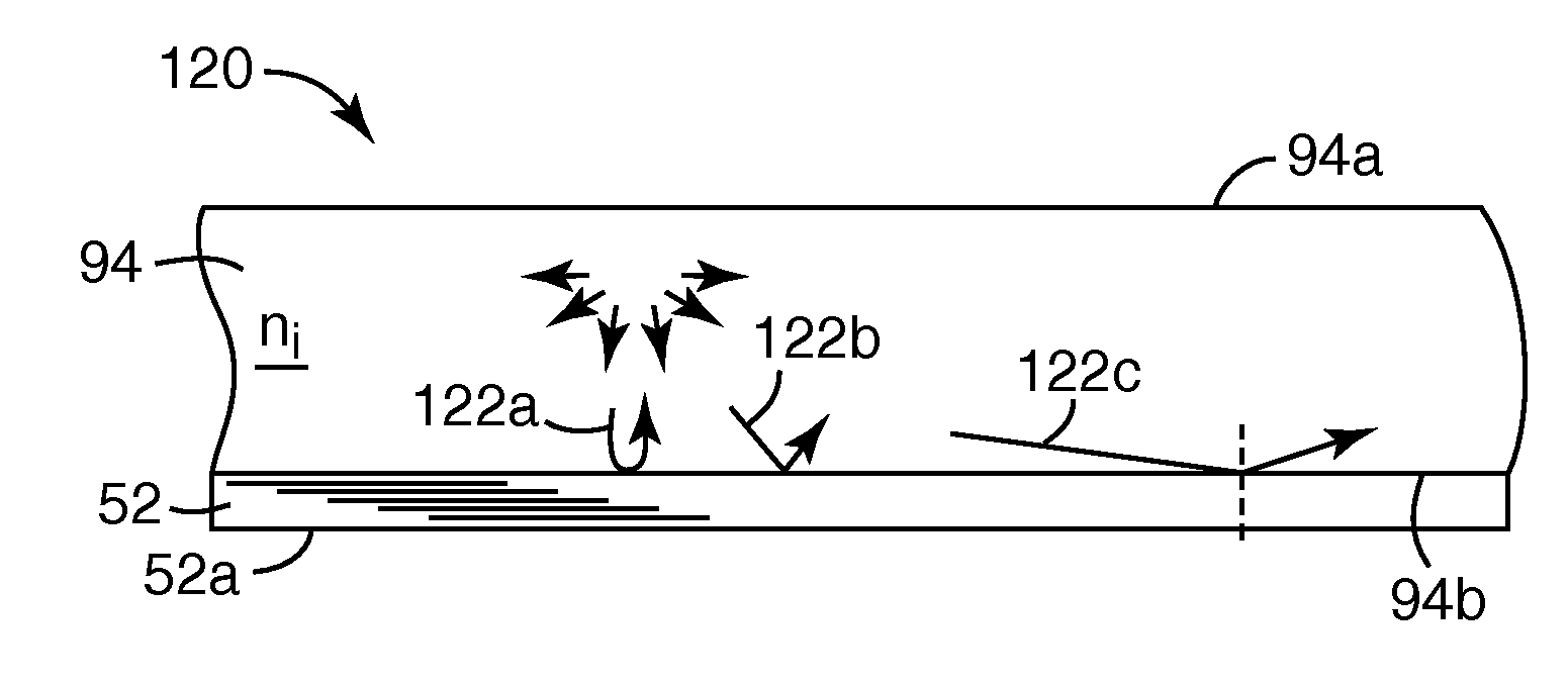
Composite mirror systems include a wideband thin film interference stack having a plurality of microlayers and an optically thick layer having a refractive index greater than air but less than the smallest refractive index of the stack. The mirror systems can provide high reflectivity for light propagating in the stack and in the optically thick layer at supercritical angles, while avoiding degradation in reflectivity if dirt or other disturbances such as absorbing materials are present at the mirror backside for example due to contact with a support structure.

Description

CROSS-REFERENCE TO RELATED APPLICATION[0001]This application is a continuation application of U.S. Ser. No. 11 / 691,769, filed Mar. 27, 2007, which claims the benefit of the filing date of Provisional Application No. 60 / 744,112 filed Mar. 31, 2006, the disclosure of which is incorporated herein by reference.FIELD OF THE INVENTION[0002]The present invention relates to mirror systems, and to mirror systems that utilize thin film interference stacks.BACKGROUND[0003]Many optical products and devices that require a high reflectivity mirror use a thin film interference stack for that purpose. Such stacks can be made economically, and can be designed to provide high reflectivity over a desired wavelength band, such as the human visible wavelength spectrum or the output spectrum of a specified light source or the sensitivity spectrum of a specified detector. The stacks can also provide reflectivity over a range of angles of the incident light. Excellent reflectivity can usually be achieved—a...

Claims


Application Information

Patent Timeline
Patent Type & Authority Applications(United States)
IPC IPC(8): G02F1/1335F21V7/04F21V1/12
CPCG02B5/0816G02B6/0011G02B5/305G02B5/285G02B5/08
Inventor WEBER, MICHAEL F.
Owner 3M INNOVATIVE PROPERTIES CO
Learn More